xp141-241-341-5.0E.pdf - 第17页
C C h h a a p p t t e e r r 2 2 Z Z e e r r o o S S e e t t t t i i n n g g s s
FK-9F98-29 XP Series Training Text for Service Engineers
Edition 5.0 XP141 – Chapter 1 Initial Adjustment Page 6 of 6
Fuji Machine Mfg. Co., Ltd.Okazaki
SMT Equipment Quality Assurance Dept.
1 – 6 CS Section
1.6 Error handling
1. In the event of an error occurring due to software or servo problems, please save the
trace data to a floppy disc, and contact FUJI with detailed information regarding the
condition of the machine at the time the error occurred.
2. When the machine is not able to shutdown using the onscreen shutdown command, shut
down the machine using one of the following procedures:
Condition Procedure
Green LED (Run) in the CPU
flashing.
Hold down the [Ready On] and [Cycle Stop]
keys simultaneously until the buzzer comes ON
Green LED (Run) in the CPU
not flashing.
Turn OFF the breaker.
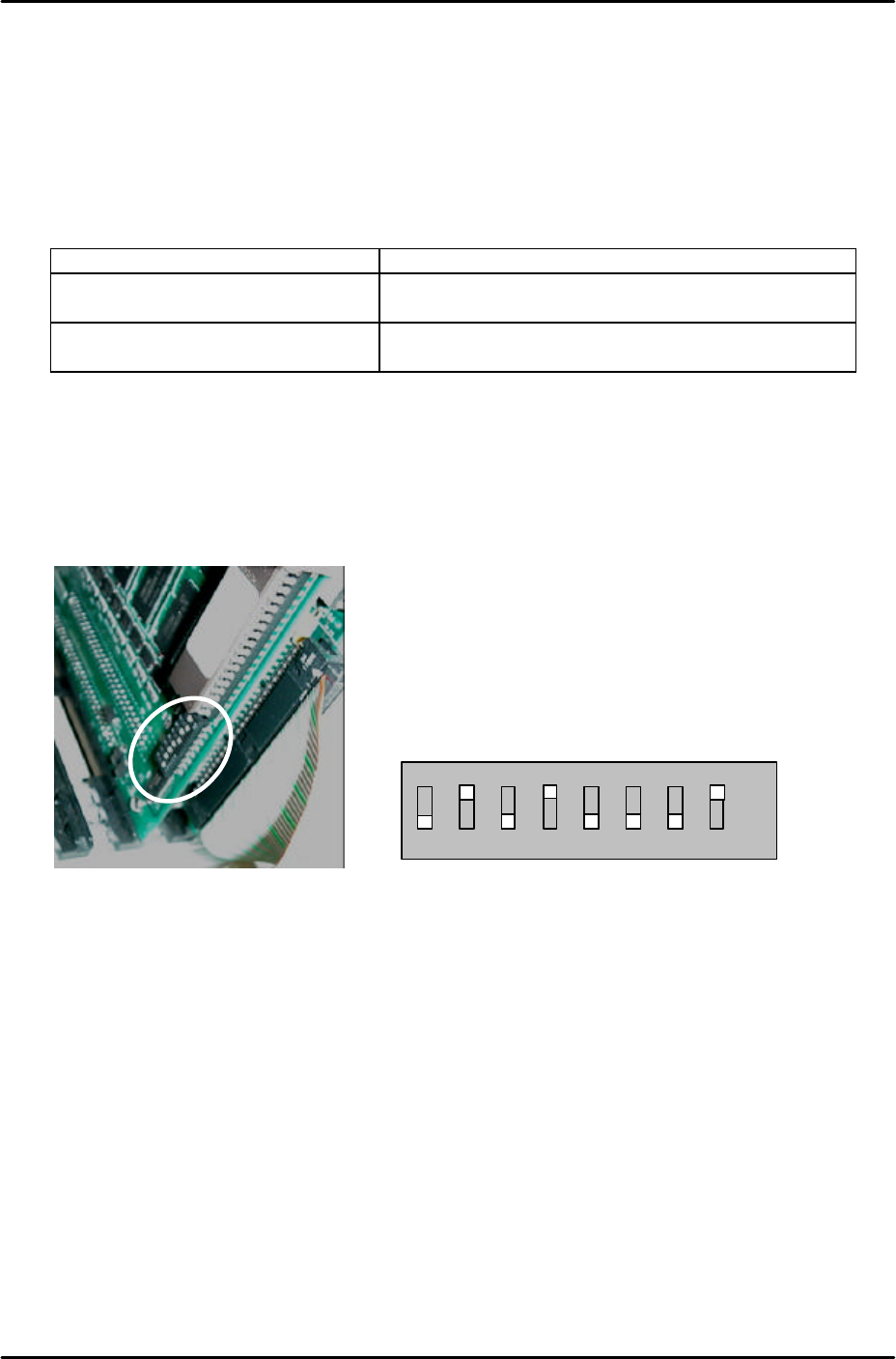
1.7 CPU Board Dip Switch Setting
1. When using software T1.21g and later versions confirm that the CPU board dip switches
are set as follows:
2. As shown the number 2, 4 and 8 dip switches should be set to ON. The remaining dip
switches should be set to OFF.
1 2 3 4 5 6 7 8
ON
OFF

C
C
h
h
a
a
p
p
t
t
e
e
r
r
2
2
Z
Z
e
e
r
r
o
o
S
S
e
e
t
t
t
t
i
i
n
n
g
g
s
s

FK-9F98-29 XP Series Training Text for Service Engineers
Edition 5.0 XP141 – Chapter 2 Zero settings Page 1 of 4
Fuji Machine Mfg. Co., Ltd. Okazaki
SMT Equipment Quality Assurance Dept.
2 – 1 CS Section
Chapter 2 – Zero Settings
2.1 Checking the digital amplifier parameters
1. Equipment: digital operator (JUSP-0P02A).
2. Press the emergency stop button to cut the 200-volt power supply to the servos.
3. Connect the digital operator to the relevant servo amplifier, (“bb” displays at the screen).
4. Press [DSPL/SET] to select the channel mode (Pn000).
5. Specify the number of the channel to be checked, then press [DATA/ENTER] to display.
6. Ensure that the values match those listed in the servo amp parameter list.
7. When you have completed checking the parameters, return to the “bb” screen.
8. If any of the servo parameter values are changed, the machine must be rebooted before
continuing with adjustments.
9. If the “multiturn” limit parameter Pn205 is changed “A.CC” will display on the amp. In this
case connect a digital operator to the amp.
10. Press the M/C emergency stop button and then release it.
11. Press [DSPL/SET] and select channel Fn000.
12. Press the up key to select channel Fn013.
13. Press [DATA/ENTER] to display [PGSET].
14. Press [DSPL/SET] and (done) displays for one second.
15. Return to Fn000 and press [DSPL/SET] to return to the initial screen, which will still
display “A.CC” until the machine is rebooted.
16. Reboot the machine and confirm that “bb” or “run’ displays on the amp.
2.2 Setting the servo amp defaults
1. Equipment: digital operator (JUSP-OPO2A).
2. Press the emergency stop button to cut the 200-volt power supply to the servos, then
set the X, Y and Z axes to their minus mechanical stoppers. For details of the location of
mechanical stoppers please refer to the diagrams in the “Supplementary Information”
section of this manual.