xp141-241-341-5.0E.pdf - 第174页
FK-9F98- 29 XP Series Training Text for Service Engineers Edition 5.0 XP241 – Chapter 8 Options Page 2 of 10 Fuji Machine Mfg. Co., Ltd. Okazaki SMT Equipment Quality Assurance Dept. 8 – 2 CS Section 2. Set the Pressure …
FK-9F98-29 XP Series Training Text for Service Engineers
Edition 5.0 XP241 – Chapter 8 Options Page 1 of 10
Fuji Machine Mfg. Co., Ltd. Okazaki
SMT Equipment Quality Assurance Dept.
8 – 1 CS Section
8.1 Board Vacuum Back Up
The optional board vacuum backup system can be used to prevent upward warping of
boards, and can also be used to detect board-clamping errors. A vacuum pressure sensor is
used to establish whether the board has been vacuumed or not. The procedure described
below is the default procedure used in the Fuji inspection process. The threshold of the
pressure sensor and other configurations in this adjustment may need to be set manually
according to the individual requirements of the user.
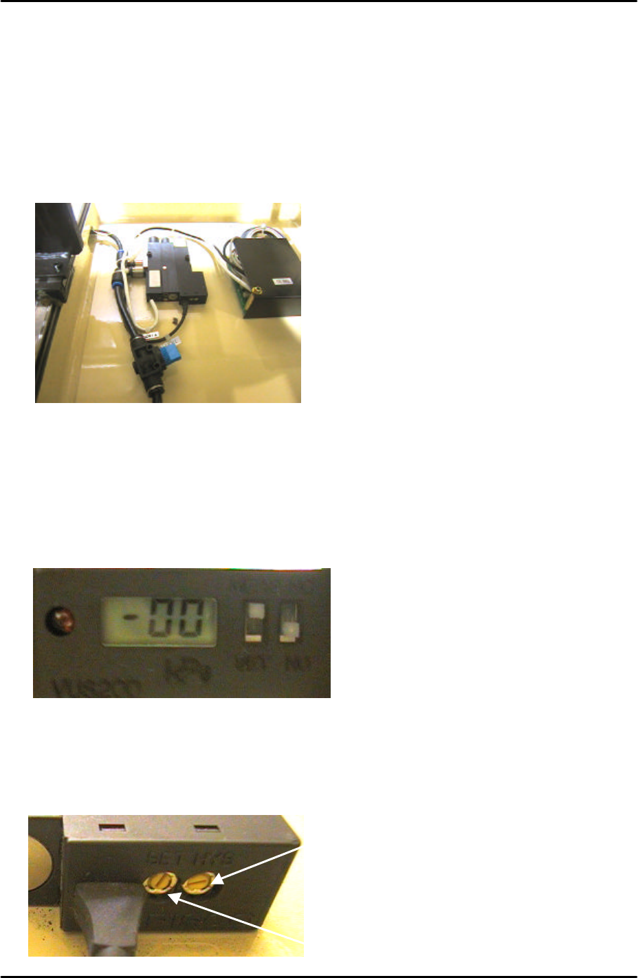
Dip Switch Setting
1. Set the N.C/N.O switch to “N.O” (Normally Open).
2. After the adjustment is finished set the pressure display switch to “MEAS”. During the
adjustment this should be set to “SET”.
Trimmer Setting
1. Set the Hysteresis Trimmer (HYS) to minimum by turning it fully counterclockwise.
MEAS
SET
N.C
N.O
Hysteresis Trimmer
Pressure Trimmer
HYS
SET
FK-9F98-29 XP Series Training Text for Service Engineers
Edition 5.0 XP241 – Chapter 8 Options Page 2 of 10
Fuji Machine Mfg. Co., Ltd. Okazaki
SMT Equipment Quality Assurance Dept.
8 – 2 CS Section
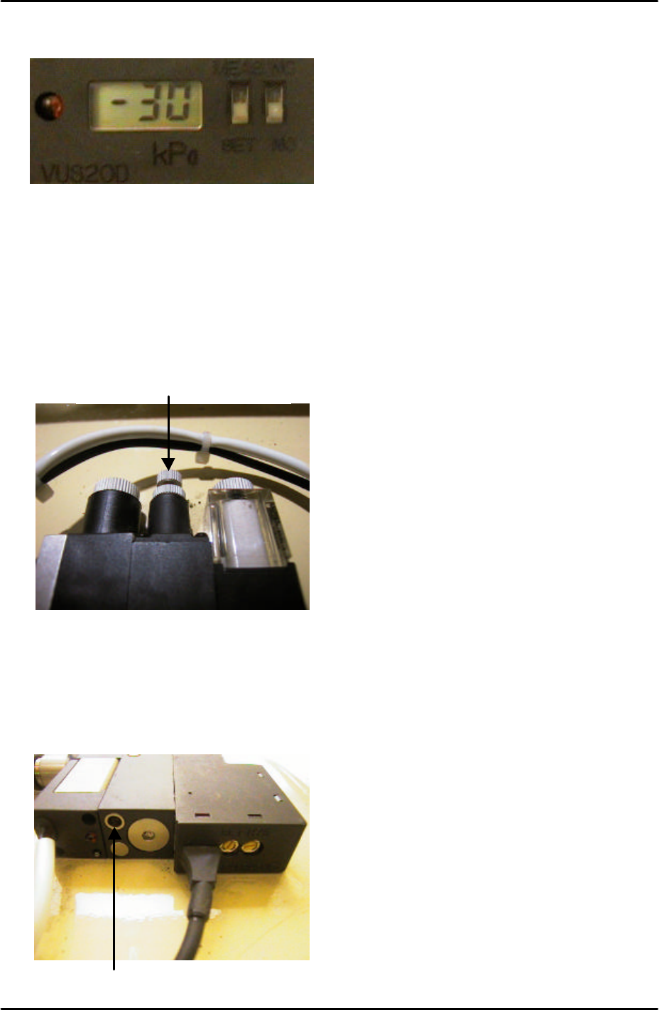
2. Set the Pressure Trimmer (SET) to –30cmHg.
3. For more details on the operation of the pressure sensor refer to the user manual in the
supplementary section of this manual.
Speed Controller Adjustment
1. Turn the air blow volume controller 3 turns from fully closed and lock.
2. Use a minus screw driver to turn the air blow release timer fully closed clockwise. From
this position turn the timer 7 turns counter clockwise. Turning the timer clockwise will
increase the air blow release time. Turning it counter clockwise will decrease the air blow
release time.
Air Blow Volume Controller
Air Blow Release Timer
FK-9F98-29 XP Series Training Text for Service Engineers
Edition 5.0 XP241 – Chapter 8 Options Page 3 of 10
Fuji Machine Mfg. Co., Ltd. Okazaki
SMT Equipment Quality Assurance Dept.
8 – 3 CS Section
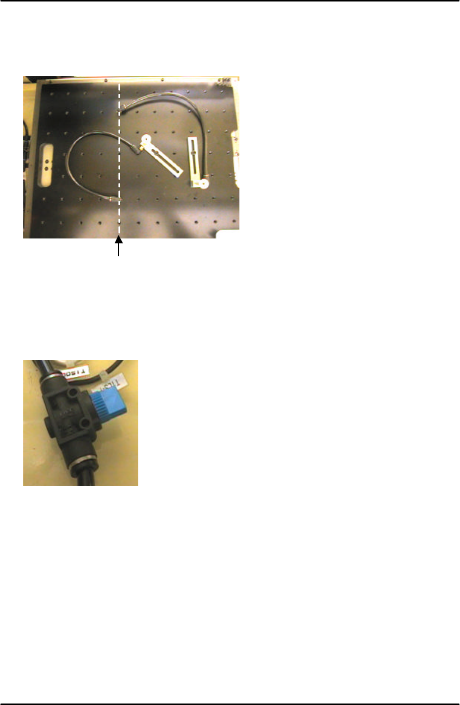
3. When setting up the vacuum back up pins on the back up plate the air terminals should
be screwed into the correct holes. The vacuum air supply is only available from the Y-
direction line 5 holes from the back up plate left hand side.
4. An air valve can be used to switch the vacuum backup air supply ON and OFF.
Only holes in this
line have a vacuum
backup air supply