xp141-241-341-5.0E.pdf - 第180页
FK-9F98- 29 XP Series Training Text for Service Engineers Edition 5.0 XP241 – Chapter 8 Options Page 8 of 10 Fuji Machine Mfg. Co., Ltd. Okazaki SMT Equipment Quality Assurance Dept. 8 – 8 CS Section Resolution measureme…
FK-9F98-29 XP Series Training Text for Service Engineers
Edition 5.0 XP241 – Chapter 8 Options Page 7 of 10
Fuji Machine Mfg. Co., Ltd. Okazaki
SMT Equipment Quality Assurance Dept.
8 – 7 CS Section
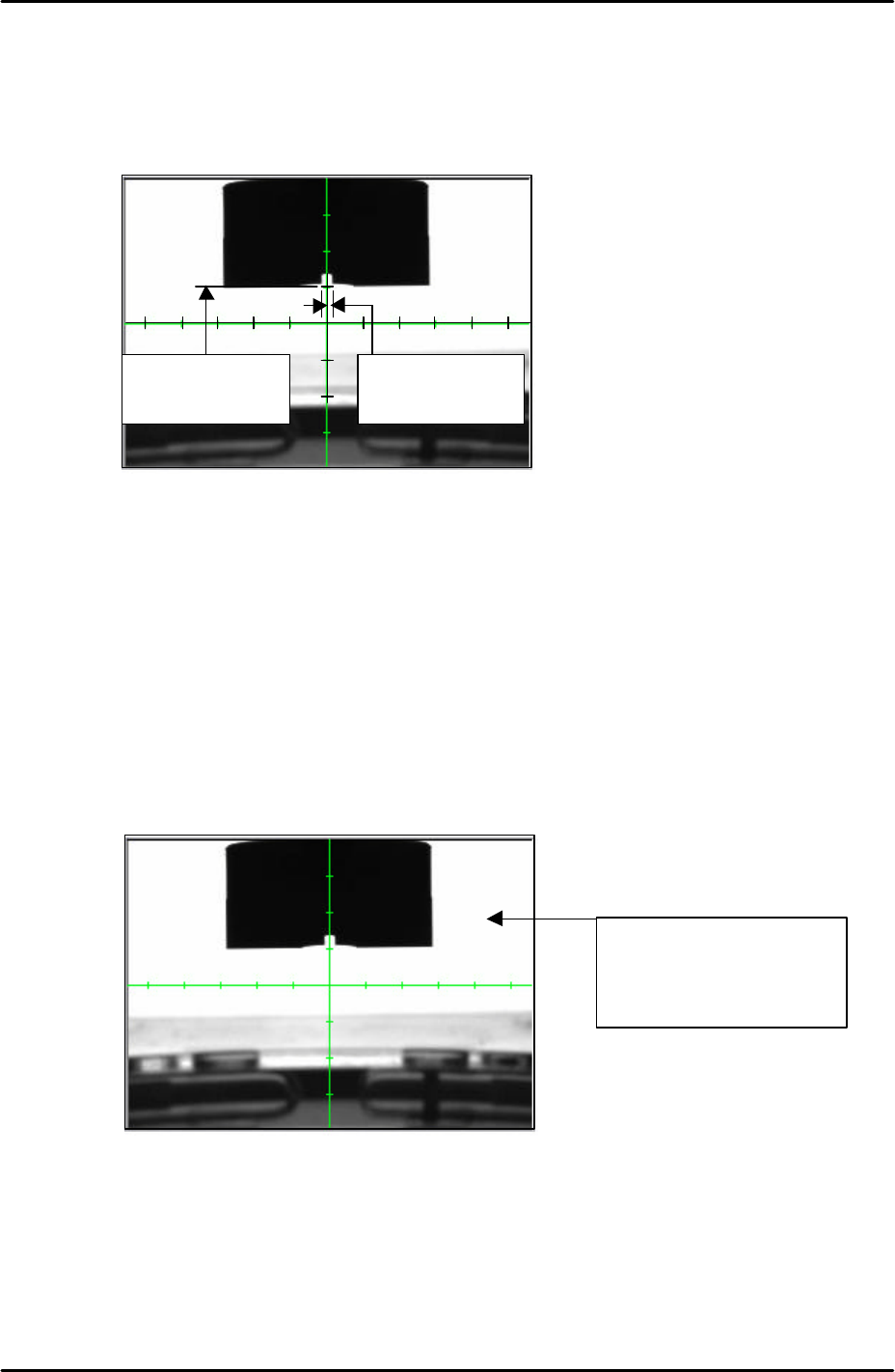
10. Adjust the coplanarity camera tilt using the tilt adjusting bolt on the camera bracket.
11. The position of the camera should be adjusted so that the bottom edge of the jig is
aligned five memory scales above the horizontal cross hair. Please see the picture
below:
12. Once the camera position has been set lock all the bolts and confirm that the position
does not change.
Camera focus and brightness
1. Adjust the camera focus so that the corner edges of the coplanarity camera nozzle jig are
as clear and sharp as possible. Adjust the focus by turning the focus ring on the end of
the camera lens. Once the focus has been set lock the focus ring set bolt.
2. After setting the focus it is necessary to set the camera brightness. Touch the white
background on the monitor to get a brightness reading as shown below:
3. The brightness value should be 210 +/- 10. If not it is necessary to adjust the
“_CoplaCamShutterSpeed” value in proper data, this has already been set to 3000 by
default. Select [Maintenance C] – [Proper Data Editor] – [Others] –
[CoplaCamShutterSpeed] and adjust the value. Lowering the value will decrease the
coplanarity camera brightness, and raising the value will increase the brightness.
4. Continue editing the value until the brightness reading is 210 +/-10.
5 memory scales
from the horizontal
cross hair
Vertical cross hair is
in the center of the
nozzle jig
Touch anywhere in the
white background to
display a brightness
reading
FK-9F98-29 XP Series Training Text for Service Engineers
Edition 5.0 XP241 – Chapter 8 Options Page 8 of 10
Fuji Machine Mfg. Co., Ltd. Okazaki
SMT Equipment Quality Assurance Dept.
8 – 8 CS Section
Resolution measurement
1. Select [Maintenance A] – [I/O Check] and turn (Y01C CoplanarityLed) ON.
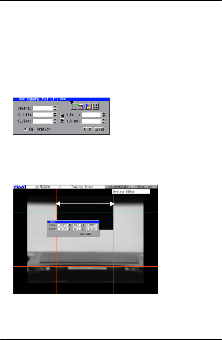
2. Select [Program] – [Template Editor].
3. Right click on the screen with a mouse and select [Utility] – [Scale Setting] to open the
“Camera Unit Ctrl” dialogue.
4. Click on the “scale setting” button to open up the scale setting screen as shown in the
picture below:
5. In the “Scale” dialogue input “20mm” in the “X_size” box.
6. Use the mouse to drag the two vertical caliper lines so that they are aligned with the left
and right edge of the coplanarity camera jig as shown in the picture below. There is no
need to align the horizontal caliper lines.
7. Once the two vertical caliper lines have been aligned with the jig and “20mm” input in
the “X_size” box, click on OK to return to the “Camera Unit Ctrl” dialogue.
8. Here the X-unit resolution figure should have been saved in the dialogue.
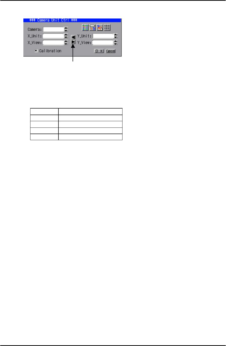
9. Now it is necessary to copy over the X_unit resolution figure to the Y_unit. To do this,
20mm
Scale
Setting
1
FK-9F98-29 XP Series Training Text for Service Engineers
Edition 5.0 XP241 – Chapter 8 Options Page 9 of 10
Fuji Machine Mfg. Co., Ltd. Okazaki
SMT Equipment Quality Assurance Dept.
8 – 9 CS Section
simply click on the right pointing arrow key on the “Camera Unit Ctrl” dialogue:
10. Having done this confirm that the resolution figures are within the tolerances shown
below:
Resolution Tolerances
X_Unit 0.0626 ~ 0.0686
X_View 40.1 ~ 43.9
Y_Unit 0.0626 ~ 0.0686
Y_View 30.06 ~ 32.94
11. Finally click on the “OK” button in the “Camera Unit Ctrl” dialogue then right click on the
screen and select return.
12. Select [Manual Operation] – [Nozzle Operation] – [Place] – [Execute] – [START] to
return the coplanarity jig to the nozzle station.
13. Finally remove the nozzle jig from the nozzle station and select [Maintenance A] – [I/O
Check] – and turn (Y01C CoplanarityLed) OFF.
14. Note that as with other cameras, the set screws for the focus and aperture rings should
be tightened securely and fastened with adhesive.
1
Click here to
copy
the X resolution
figures to Y