xp141-241-341-5.0E.pdf - 第190页
FK-9F98- 29 XP Series Training Text for Service Engineers Edition 5.0 XP241 – Chapter 9 New MTU Adjustment Page 7 of 21 Fuji Machine Mfg. Co., Ltd. Okazaki SMT Equipment Quality Assurance Dept. 9 – 7 CS Section 6. Select…
FK-9F98-29 XP Series Training Text for Service Engineers
Edition 5.0 XP241 – Chapter 9 New MTU Adjustment Page 6 of 21
Fuji Machine Mfg. Co., Ltd. Okazaki
SMT Equipment Quality Assurance Dept.
9 – 6 CS Section
2. Verify that the roller rotates with the belt when the belt is pulled manually.
3. Remove the jumper and replace the “35BKT1-CN2” cable in the side 1 electric box and
confirm the brake is on even when the servo power is OFF.
9.10 T-Tray origin (magazine adjustment and measurement)
1. Jog the T-axis until the right hand side of slot [41,42] is level with the U axis conveyor rail.
Use the dial gages and jig (Z9731ADEPJ8131):
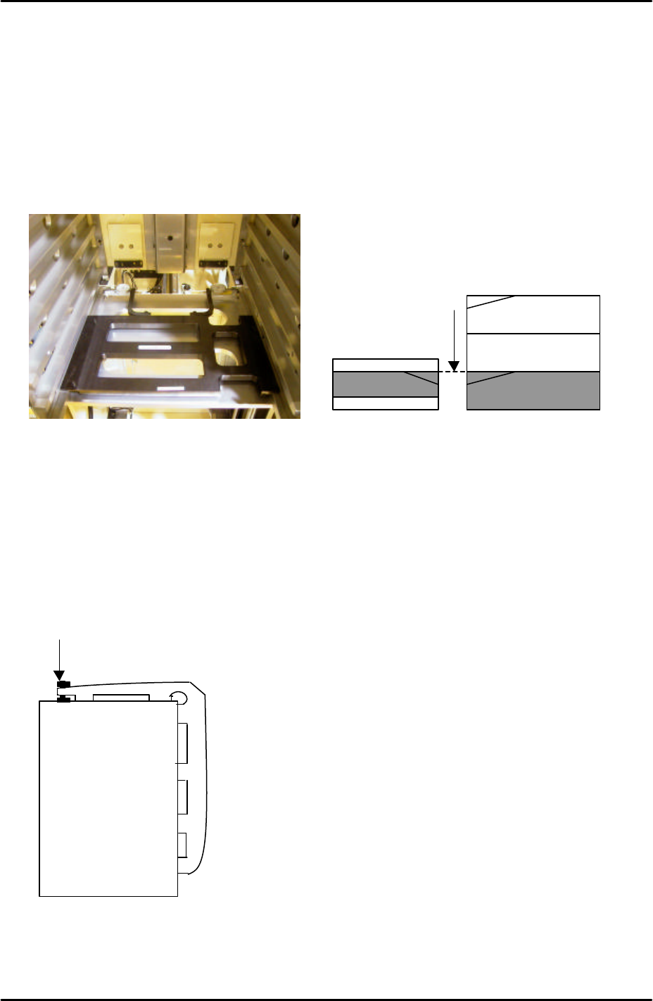
2. With the T-axis in the same position measure the height difference between the left side
of slot [41, 42] and the U axis conveyor rail. The height of the magazine slot should be
0.03mm higher than that of the U axis conveyor rail. The reason for this is that the MTU
magazine is fixed at the right hand side (when viewed from the machine rear) but not at
the left-hand side. When trays and tray parts are loaded on the left-hand side it is
weighed down and lowers slightly in relation to the right hand side.
3. If necessary adjust the height of the left hand side of slot [41,42] using the bolt on top of
the magazine, see diagram below:
4. Jog the T axis so that slot [01,02] is roughly level with the U axis conveyor rail.
5. Use the dial gage and jig to find the position where the right hand side of slot [01,02] is
0.04mm above the U axis conveyor rail.
Adjust here
Magazine [41,42]
U axis
The U axis conveyor
and slot [41,42] of the
magazine are level
FK-9F98-29 XP Series Training Text for Service Engineers
Edition 5.0 XP241 – Chapter 9 New MTU Adjustment Page 7 of 21
Fuji Machine Mfg. Co., Ltd. Okazaki
SMT Equipment Quality Assurance Dept.
9 – 7 CS Section
6. Select [Maintenance C] – [Proper Data Editor] – [TRAY] – [T_TrayOrg] – [Direct Servo
Input] to save the current T axis position as “T_TrayOrg” in proper data.
9.11 Guide rail adjustment
1. Place an empty tray pallet in slot [01,02] and bring it to the “T_TrayOrg” position.
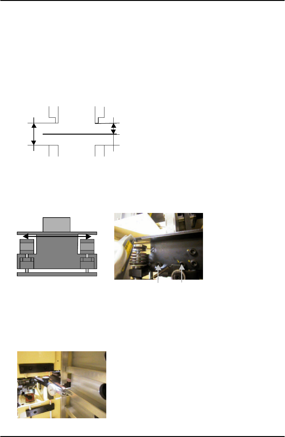
2. Adjust the upper guide rails so that they are 9mm above the tray pallet surface.
3. Adjust the lower guide rails so that they are 19mm beneath the upper guide rails.
9.12 U axis clamper parallelism check and adjustment
1. Use an extension bar to attach a dial gage to the placing head and adjust the parallelism
of the U axis shuttle so that it is parallel to the X-axis. Tolerance is 0.03mm. Refer to the
diagram and photo below:
9.13 Shuttle rail position adjustment
1. Use a dial gage to measure the width of all the slots. Find the average slot to use as a
reference, refer to the photo below:
9mm
19mm
Tray Pallet
MC Front
To adjust the parallelism loosen these
two bolts
Use a dial gage to measure the width
of all the slots, and use the slot with
an average width as the reference.
FK-9F98-29 XP Series Training Text for Service Engineers
Edition 5.0 XP241 – Chapter 9 New MTU Adjustment Page 8 of 21
Fuji Machine Mfg. Co., Ltd. Okazaki
SMT Equipment Quality Assurance Dept.
9 – 8 CS Section
2. Adjust the position of the shuttle rails so that they are aligned with the reference slot,
tolerance is 0.05mm.
3. Be careful when measuring the alignment as the first few centimeters of the shuttle rails
are tapered. Measure at the point where the shuttle rail is straight.
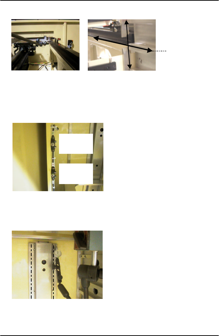
9.14 Tray pusher adjustment 1
1. Set the speed controllers for the tray pusher as follows:
2. Turn I/O Y033: TrayPusherBwd OFF, and I/O Y032 TrayPusherFwd ON to bring the
pusher to its forward position.
3. Attach a dial gage stand to the magazine and set the dial gage tip on the pusher as
shown below:
4. Measure the flatness of the left and right hand pusher panels. Measure from top to
bottom as illustrated by the dotted lines in the photo above.
5. If necessary loosen the installation bolts on the panels, and adjust the flatness with the
Measure along this line
Fwd: ¾ turn
from fully
closed
Bwd: 5 turns
from fully
closed