xp141-241-341-5.0E.pdf - 第197页
FK-9F98- 29 XP Series Training Text for Service Engineers Edition 5.0 XP241 – Chapter 9 New MTU Adjustment Page 14 of 21 Fuji Machine Mfg. Co., Ltd. Okazaki SMT Equipment Quality Assurance Dept. 9 – 14 CS Section 9.20 Tr…
FK-9F98-29 XP Series Training Text for Service Engineers
Edition 5.0 XP241 – Chapter 9 New MTU Adjustment Page 13 of 21
Fuji Machine Mfg. Co., Ltd. Okazaki
SMT Equipment Quality Assurance Dept.
9 – 13 CS Section
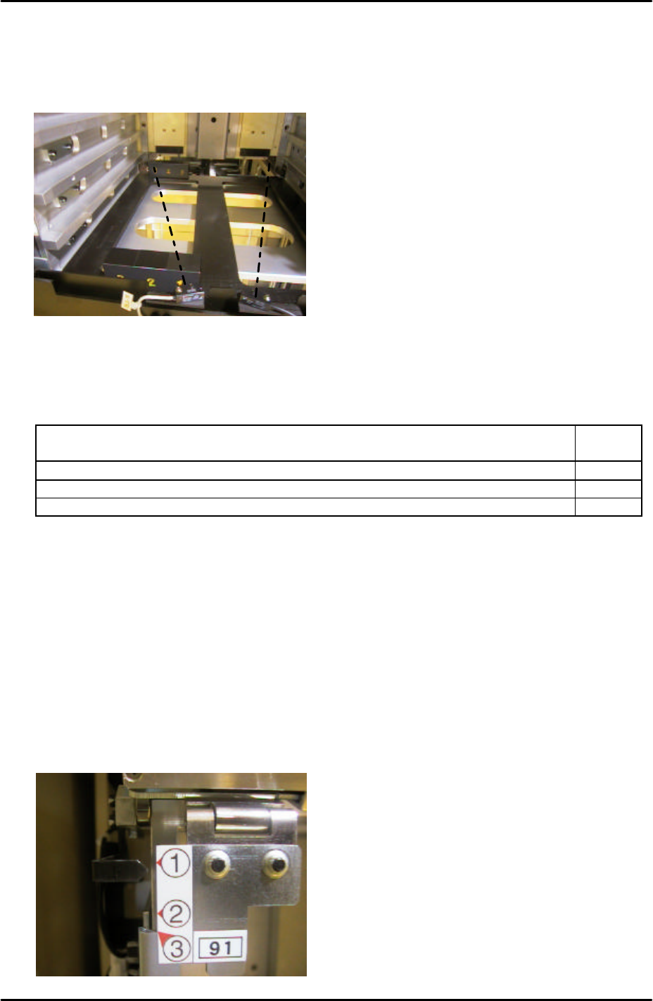
9.18 Tray height check sensor and [T_TrayEmptyOrg] measurement
1. Put the tray pallet jig in slot [01,02] and bring it to the [T_TrayOrg] position.
2. Place two of the “three step” jigs on the tray pallet jig as shown below:
3. The path of the sensor beam is illustrated by the dotted line in the photo above.
4. Adjust the height of the “X03A TrayHeightChk1” sensor transmitter and receiver as
follows:
Jig Combination I/O
Status
Step 2 + 2 of the step jigs are in line with the sensor transmitter and receiver ON
Step 2 + 3 of the step jigs are in line with the sensor transmitter and receiver ON
Step 3 + 3 of the step jigs are in line with the sensor transmitter and receiver OFF
5. Repeat the adjustment for the “X03B TrayHeightChk2” sensor transmitter and receiver.
6. Remove the two “three step” jigs from the MTU, leaving only the tray pallet jig.
7. Slowly jog the T-axis up until both “X03A TrayHeightChk1” and “X03B TrayHeightChk2”
come ON. This position is “T_TrayEmptyOrg”. Select [Maintenance C] – [Proper Data
Editor] – [T_TrayEmptyOrg] – [Direct Servo Input] to save the current counter value in
proper data.
9.19 Tray shutter check sensor adjustment
1. Adjust the position of the sensor bracket so that when the tray shutter is at position 1 the
sensor LED is OFF, and comes ON when raising the shutter by 1mm.
X032 TrayShutOpnChk
FK-9F98-29 XP Series Training Text for Service Engineers
Edition 5.0 XP241 – Chapter 9 New MTU Adjustment Page 14 of 21
Fuji Machine Mfg. Co., Ltd. Okazaki
SMT Equipment Quality Assurance Dept.
9 – 14 CS Section
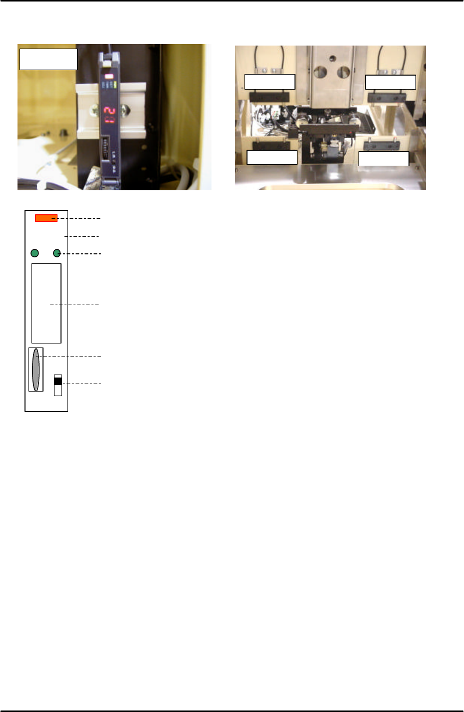
9.20 Tray pallet interference check sensor amplifier adjustment
1. Press the dial switch once [the RUN light in the Mode Display flashes and “AA” is
displayed on the Digital Display].
2. Turn the dial switch so that the Mode Display turns from RUN to SET.
3. Press and hold the dial switch for more than 3 seconds [HP displays on the Digital
Display and the Mode Lights come ON].
4. Press the dial switch once [SET in the Mode Display flashes and “2P” is displayed on the
Digital Display].
5. Press the dial switch once [“2P” displayed on the Digital Display flashes].
6. Keep turning the dial switch until numbers (0~100), are displayed on the Digital Display
and the Mode Lights come ON.
7. Confirm that the value displayed on the Digital Display is greater than 3.
8. Turn the dial switch until a flashing “2P” displays on the Digital Display.
9. Make sure the sensor is not blocked and press the dial switch once [the 2 in “2P”
LO DO
RUN
SET
TMR
ADJ
Digital Display
Operation Light
L-ON/D-ON Changeover Switch
Dial Switch
Mode Display
Mode Lights
Sensors
Sensors
Sensors
Sensors
Amplifier
FK-9F98-29 XP Series Training Text for Service Engineers
Edition 5.0 XP241 – Chapter 9 New MTU Adjustment Page 15 of 21
Fuji Machine Mfg. Co., Ltd. Okazaki
SMT Equipment Quality Assurance Dept.
9 – 15 CS Section
flashes].
10. Block the sensor and press the dial switch once. A number displays on the Digital
Display. Confirm that this number is greater than 10.
11. Press the dial switch once [SET in the Mode Display flashes and “2P” is displayed on the
Digital Display].
12. Turn the dial switch until RUN flashes in the Mode Display and “AA” is displayed on the
Digital Display.
13. Press the dial switch once [RUN in the Mode Display stops flashing and a number
appears in the Digital Display].
14. The sensor amplifier adjustment is now complete, confirm that the changeover switch is
set to “LO”.
15. Confirm the sensor operation by I/O. The I/O output X03C TraySetChk should be OFF
when the sensor is interrupted and ON when there is no interruption.
Sensor Condition Output
Interrupted X
Uninterrupted O
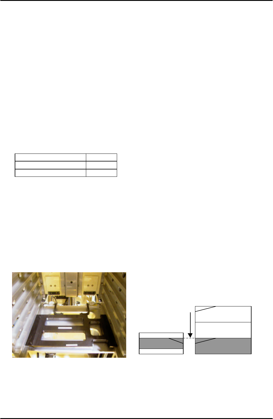
9.21 Tray pitch offset measurement
1. Select [Manual Operation] – [Tray Operation] – [Tray height measurement].
2. After tray height measurement is completed select slot [11,12] – [Move Elevator] to go to
the tray transference position for that slot.
3. Measure the difference in height between the right hand of the slot and the U axis
conveyor rail. Use two dial gages and the jig shown in the photo (Z9731ADEPJ8131):
4. At this position the right hand magazine slot should be 0.04mm higher than the U axis
conveyor rail. If this is not the case it is necessary to input an offset.
5. Select [Maintenance C] – [Proper Data Editor] – [Tray] – [_ElevatorOfst2] and input the
offset value as follows:
Magazine [41,42]
U axis
Measure height of the
magazine slots relative
to the U axis and input
offsets in proper data.