xp141-241-341-5.0E.pdf - 第199页
FK-9F98- 29 XP Series Training Text for Service Engineers Edition 5.0 XP241 – Chapter 9 New MTU Adjustment Page 16 of 21 Fuji Machine Mfg. Co., Ltd. Okazaki SMT Equipment Quality Assurance Dept. 9 – 16 CS Section Measure…
FK-9F98-29 XP Series Training Text for Service Engineers
Edition 5.0 XP241 – Chapter 9 New MTU Adjustment Page 15 of 21
Fuji Machine Mfg. Co., Ltd. Okazaki
SMT Equipment Quality Assurance Dept.
9 – 15 CS Section
flashes].
10. Block the sensor and press the dial switch once. A number displays on the Digital
Display. Confirm that this number is greater than 10.
11. Press the dial switch once [SET in the Mode Display flashes and “2P” is displayed on the
Digital Display].
12. Turn the dial switch until RUN flashes in the Mode Display and “AA” is displayed on the
Digital Display.
13. Press the dial switch once [RUN in the Mode Display stops flashing and a number
appears in the Digital Display].
14. The sensor amplifier adjustment is now complete, confirm that the changeover switch is
set to “LO”.
15. Confirm the sensor operation by I/O. The I/O output X03C TraySetChk should be OFF
when the sensor is interrupted and ON when there is no interruption.
Sensor Condition Output
Interrupted X
Uninterrupted O
9.21 Tray pitch offset measurement
1. Select [Manual Operation] – [Tray Operation] – [Tray height measurement].
2. After tray height measurement is completed select slot [11,12] – [Move Elevator] to go to
the tray transference position for that slot.
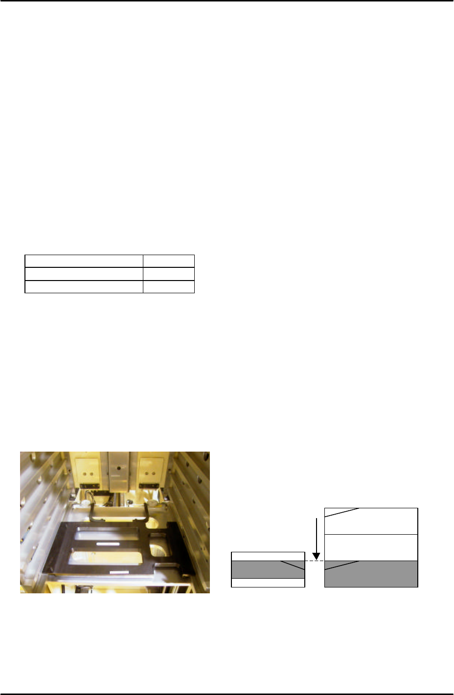
3. Measure the difference in height between the right hand of the slot and the U axis
conveyor rail. Use two dial gages and the jig shown in the photo (Z9731ADEPJ8131):
4. At this position the right hand magazine slot should be 0.04mm higher than the U axis
conveyor rail. If this is not the case it is necessary to input an offset.
5. Select [Maintenance C] – [Proper Data Editor] – [Tray] – [_ElevatorOfst2] and input the
offset value as follows:
Magazine [41,42]
U axis
Measure height of the
magazine slots relative
to the U axis and input
offsets in proper data.
FK-9F98-29 XP Series Training Text for Service Engineers
Edition 5.0 XP241 – Chapter 9 New MTU Adjustment Page 16 of 21
Fuji Machine Mfg. Co., Ltd. Okazaki
SMT Equipment Quality Assurance Dept.
9 – 16 CS Section
Measured Value Offset Value
+ 0.04mm 0.00
+ 0.03mm 0.01
+ 0.05mm -0.01
6. Repeat for all remaining slots:
Slot Offset
[11,12] _ElevatorOfst2
[21,22] _ElevatorOfst3
[31,32] _ElevatorOfst4
[41,42] _ElevatorOfst5
[51,52] _ElevatorOfst6
[61,62] _ElevatorOfst7
[71,72] _ElevatorOfst8
[81,82] _ElevatorOfst9
[91,92] _ElevatorOfst10
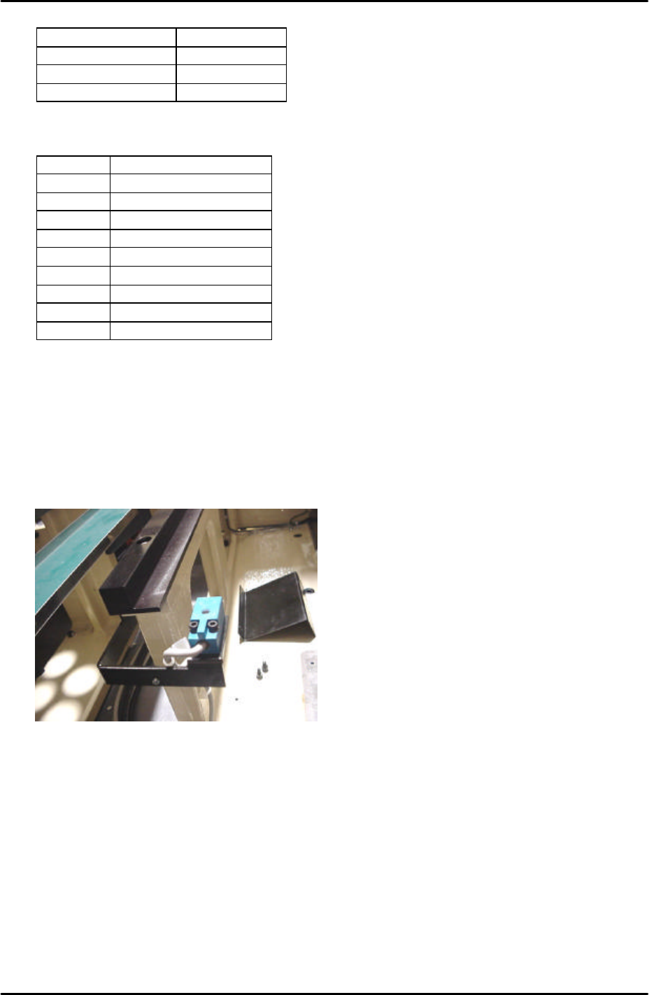
9.22 Tray pickup position check sensor adjustment
1. Put a tray pallet in slot [01,02] and bring it to the tray transference position by selecting
[Manual Operation] – [Tray Operation] – [01,02] – [Move Elevator].
2. Select [Manual Operation] – [Tray Operation] – [Shuttle Forward] – to move the tray pallet
to its forward end.
3. At this position set the height of the tray pickup position check sensor so that there is a
gap of 2.5mm between the top surface of the sensor and the bottom surface of the tray
pallet.
4. Select [Maintenance A] – [I/O Check] – [X039 P.PosTrayDetect] to monitor the sensor
signal. When the sensor is interrupted the I/O is OFF, but the LED is ON.
5. Adjust the position of the sensor in the Y direction so that the LED just comes ON and
then fix it 3mm further in that direction.
6. Check the sensor operation by I/O.
FK-9F98-29 XP Series Training Text for Service Engineers
Edition 5.0 XP241 – Chapter 9 New MTU Adjustment Page 17 of 21
Fuji Machine Mfg. Co., Ltd. Okazaki
SMT Equipment Quality Assurance Dept.
9 – 17 CS Section
9.23 Tray catch stopper adjustment
1. For this adjustment do not use the tray pallet jig (Z9631DEPJ3740) because it interferes.
Use a normal tray pallet instead.
2. Set a tray pallet in slot [51,52].
3. Select [Manual Operation] – [Tray Operation] – [Tray height measurement].
4. After tray height measurement is complete select slot [51,52] – [Move Elevator] to go to
the tray transference position for that slot.
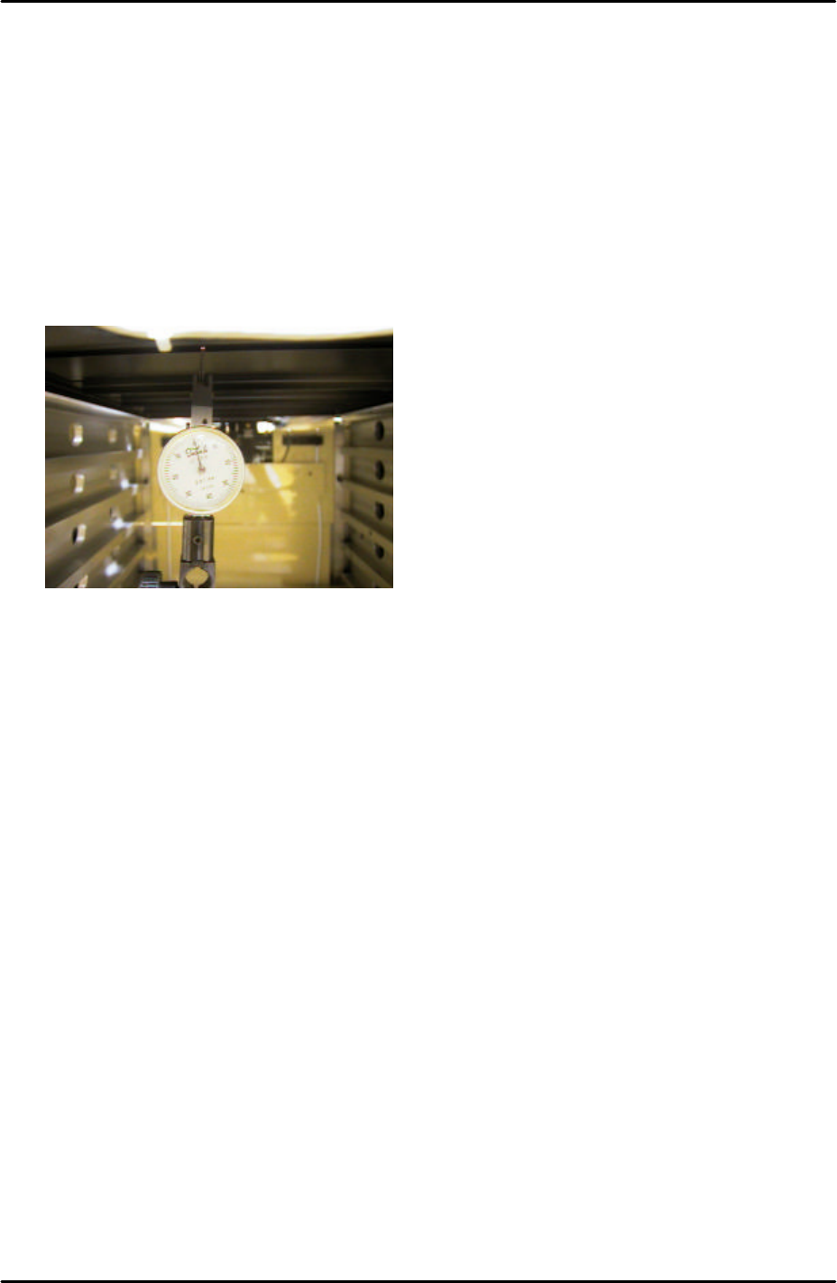
5. Set a dial gage to 0 on the tray pallet as shown in the photo:
6. Move the tray pallet forward by selecting [Manual Operation] – [Tray Operation] – [Shuttle
Forward].
7. Retract the tray pallet by selecting [Manual Operation] – [Tray Operation] – [Shuttle
Retract].
8. At this position the dial gage should read 0 +/- 0.1mm. If not adjust and lock the tray
catch stopper.
9. After adjusting the stopper so that the dial gage reads 0 +/- 0.1mm, advance and retract
the tray pallet again and confirm the dial gage reading is within tolerance.