xp141-241-341-5.0E.pdf - 第200页
FK-9F98- 29 XP Series Training Text for Service Engineers Edition 5.0 XP241 – Chapter 9 New MTU Adjustment Page 17 of 21 Fuji Machine Mfg. Co., Ltd. Okazaki SMT Equipment Quality Assurance Dept. 9 – 17 CS Section 9.23 Tr…
FK-9F98-29 XP Series Training Text for Service Engineers
Edition 5.0 XP241 – Chapter 9 New MTU Adjustment Page 16 of 21
Fuji Machine Mfg. Co., Ltd. Okazaki
SMT Equipment Quality Assurance Dept.
9 – 16 CS Section
Measured Value Offset Value
+ 0.04mm 0.00
+ 0.03mm 0.01
+ 0.05mm -0.01
6. Repeat for all remaining slots:
Slot Offset
[11,12] _ElevatorOfst2
[21,22] _ElevatorOfst3
[31,32] _ElevatorOfst4
[41,42] _ElevatorOfst5
[51,52] _ElevatorOfst6
[61,62] _ElevatorOfst7
[71,72] _ElevatorOfst8
[81,82] _ElevatorOfst9
[91,92] _ElevatorOfst10
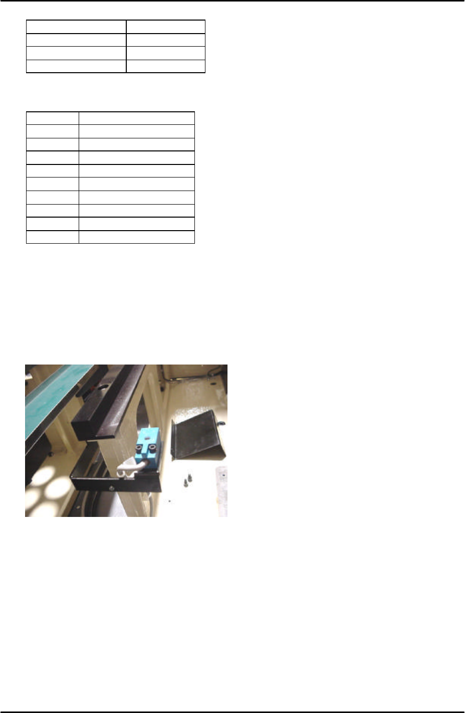
9.22 Tray pickup position check sensor adjustment
1. Put a tray pallet in slot [01,02] and bring it to the tray transference position by selecting
[Manual Operation] – [Tray Operation] – [01,02] – [Move Elevator].
2. Select [Manual Operation] – [Tray Operation] – [Shuttle Forward] – to move the tray pallet
to its forward end.
3. At this position set the height of the tray pickup position check sensor so that there is a
gap of 2.5mm between the top surface of the sensor and the bottom surface of the tray
pallet.
4. Select [Maintenance A] – [I/O Check] – [X039 P.PosTrayDetect] to monitor the sensor
signal. When the sensor is interrupted the I/O is OFF, but the LED is ON.
5. Adjust the position of the sensor in the Y direction so that the LED just comes ON and
then fix it 3mm further in that direction.
6. Check the sensor operation by I/O.
FK-9F98-29 XP Series Training Text for Service Engineers
Edition 5.0 XP241 – Chapter 9 New MTU Adjustment Page 17 of 21
Fuji Machine Mfg. Co., Ltd. Okazaki
SMT Equipment Quality Assurance Dept.
9 – 17 CS Section
9.23 Tray catch stopper adjustment
1. For this adjustment do not use the tray pallet jig (Z9631DEPJ3740) because it interferes.
Use a normal tray pallet instead.
2. Set a tray pallet in slot [51,52].
3. Select [Manual Operation] – [Tray Operation] – [Tray height measurement].
4. After tray height measurement is complete select slot [51,52] – [Move Elevator] to go to
the tray transference position for that slot.
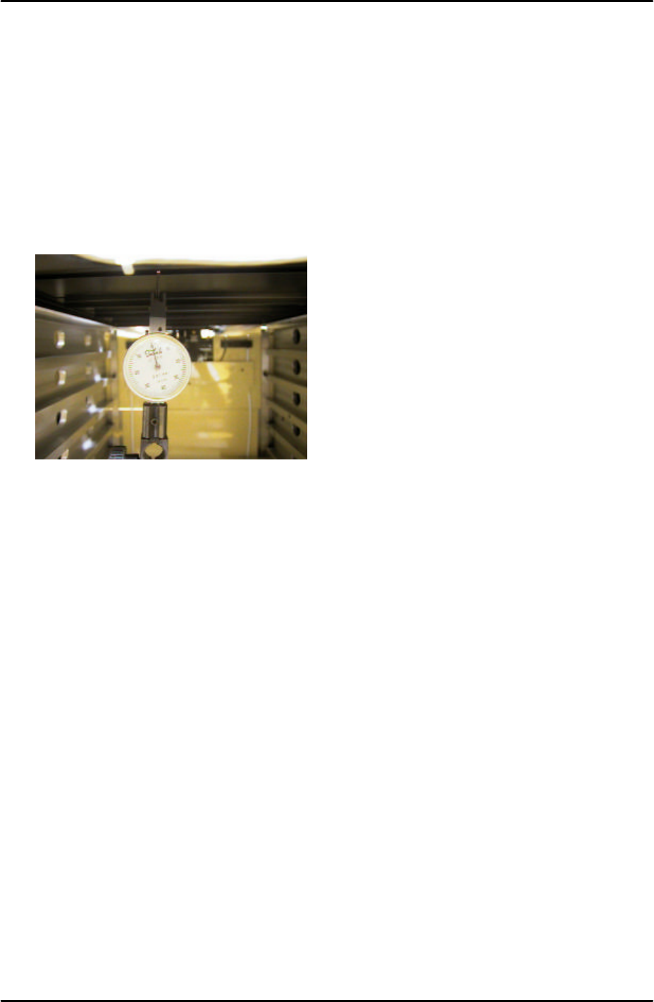
5. Set a dial gage to 0 on the tray pallet as shown in the photo:
6. Move the tray pallet forward by selecting [Manual Operation] – [Tray Operation] – [Shuttle
Forward].
7. Retract the tray pallet by selecting [Manual Operation] – [Tray Operation] – [Shuttle
Retract].
8. At this position the dial gage should read 0 +/- 0.1mm. If not adjust and lock the tray
catch stopper.
9. After adjusting the stopper so that the dial gage reads 0 +/- 0.1mm, advance and retract
the tray pallet again and confirm the dial gage reading is within tolerance.
FK-9F98-29 XP Series Training Text for Service Engineers
Edition 5.0 XP241 – Chapter 9 New MTU Adjustment Page 18 of 21
Fuji Machine Mfg. Co., Ltd. Okazaki
SMT Equipment Quality Assurance Dept.
9 – 18 CS Section
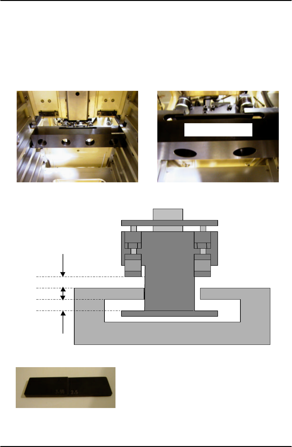
9.24 Shuttle clamp position check
1. Temporarily set the large block jig (Z9631ADEPJ8172) in the center of slot [41,42].
2. Move the T-axis so that slot [51,52] moves to the tray transference position.
3. Position the large block jig so that the cut out section hooks over the shuttle clamper as
shown in the photographs below. Make sure that the large block jig is pushed as far
forward as possible so that it is right up against the MTU guide rails:
4. Under these conditions check that the front and back clearances between the shuttle
clamper and jig are within tolerance as shown in the following diagram:
5. Use a feeler gage jig or similar object to measure the gaps:
6. If the clearance is not within tolerance recheck the shuttle clamping position adjustment
(9.16) and the tray catch stopper adjustment (9.23).
Z9631ADEPJ8172
2.5mm to 3.55mm
2.5mm to 3.55mm
Z9631ADEPJ8172
3.55 2.5