xp141-241-341-5.0E.pdf - 第206页
FK-9F98- 29 XP Series Training Text for Service Engineers Edition 5.0 XP341E Supplement Page 1 of 2 Fuji Machine Mfg. Co., Ltd. Okazaki 1 SMT Equipment Quality Assurance Dept. CS Section NOTE: For the most part the XP241…
X
X
P
P
3
3
4
4
1
1
E
E
S
S
u
u
p
p
p
p
l
l
e
e
m
m
e
e
n
n
t
t
Machine Mfg. Co., Ltd.
Solutions for Modern Technology
FK-9F98-29 XP Series Training Text for Service Engineers
Edition 5.0 XP341E Supplement Page 1 of 2
Fuji Machine Mfg. Co., Ltd. Okazaki
1 SMT Equipment Quality Assurance Dept.
CS Section
NOTE: For the most part the XP241E manual can be used to make adjustments and
checks on XP341E machines. However there are a few procedures that are different for
XP341E machines. These are described here.
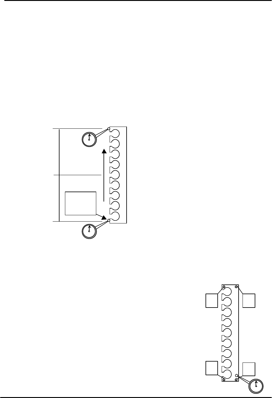
3.8 Measuring the parallelism and flatness of the nozzle station
1. Equipment: Lever type dial gage (0.01mm). Extension bar.
Nozzle station parallelism measurement
1. Use the extension bar to attach a dial gage to the placing head.
2. Refer to the diagram below and use one end of the nozzle station as the reference
point.
3. Move the placing head along the Y-axis to check the parallelism of the nozzle
station.
4. Tolerance is 0.10mm/500mm, if the value is out of tolerance please contact FUJI.
Nozzle station flatness measurement
1. Use the extension bar to attach a dial gage to the placing
head.
2. Refer to the adjacent diagram and use position A as the
reference point.
3. Run the dial gage over the nozzle station surface and check
the height at the four corners of the station. Any deviation in
height should be within 0.10mm. If out of tolerance please
contact FUJI.
Reference
position
0
250
500
+ ?? -
D
C B
A
FK-9F98-29 XP Series Training Text for Service Engineers
Edition 5.0 XP341E Supplement Page 2 of 2
Fuji Machine Mfg. Co., Ltd. Okazaki
2 SMT Equipment Quality Assurance Dept.
CS Section
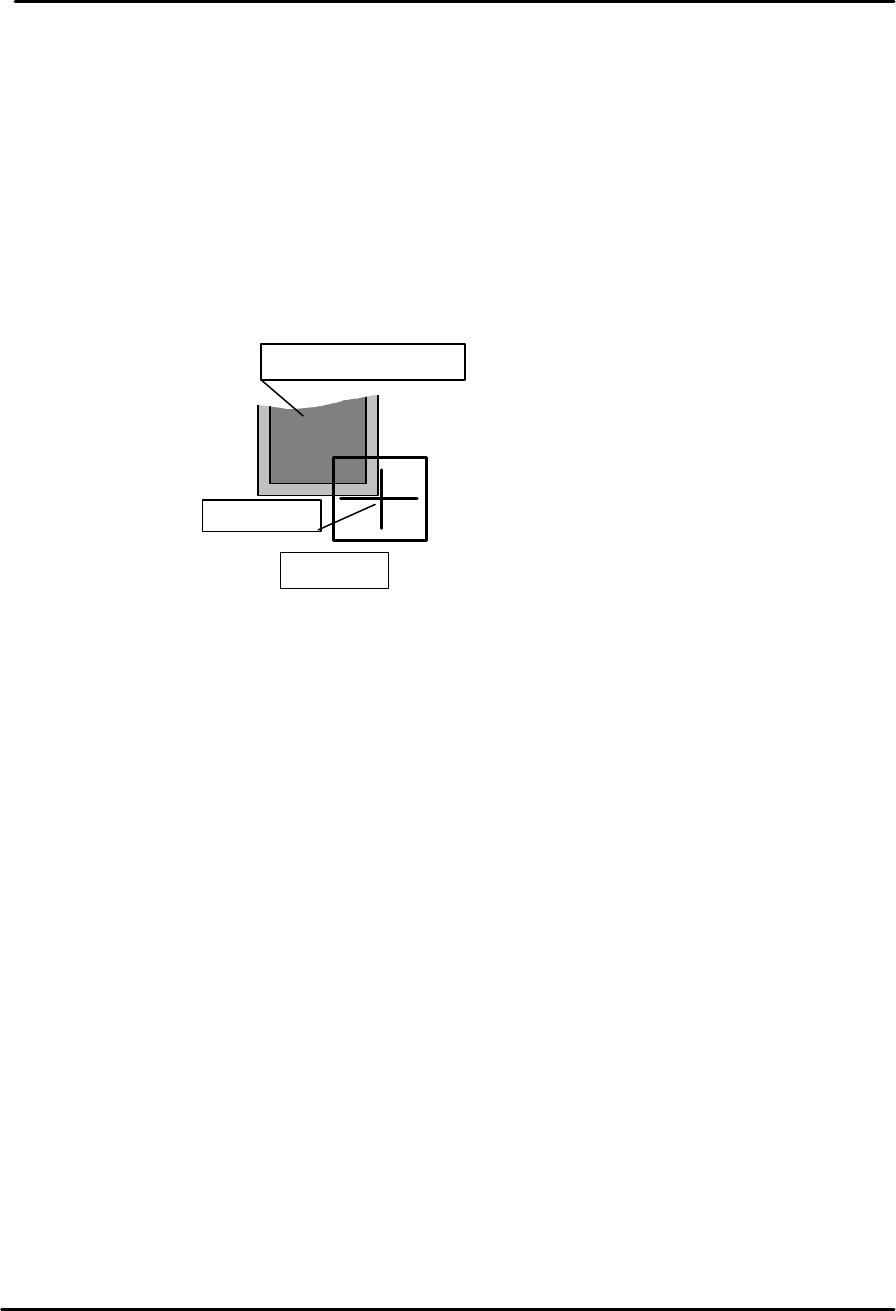
6.11 Measuring the parts reject position
Large parts reject position
1. Equipment: Nozzle jig (Z95314DEPJ0070).
2. Select [Maintenance A] – [Jog] – [Fiducial Camera] and display the cross hairs on
the screen.
3. From the machine front [side 1] move the fiducial camera over the large parts reject
tray until the cross hairs are centered on the bottom right corner of the tray as shown
in the diagram below:
4. Select [Maintenance C] – [Proper Data Editor] – [DISPOSE_POSITION] –
[X_Disposal 2] and [Y_Disposal 2] – [Direct Servo Input] to save the current X and Y
counter values to proper data.
5. Select [Maintenance A] – [I/O Check] – [Y021 NozzleUnhold] – [OFF] and attach the
nozzle jig to the placing head.
6. Select [Maintenance A] – [Jog] and carefully inch the nozzle jig above the surface of
the reject parts tray.
7. Press the emergency stop button to cut the 200 volt power supply to the servos and
then manually descend the Z-axis until the nozzle jig contacts the surface of the
reject parts tray.
8. Select [Maintenance C] – [Proper Data Editor] – [DISPOSE_POSITION] –
[Z_Disposal 2] – [Direct Servo Input] to save the current Z-axis position in proper
data.
Large parts reject tray
Center mark
M/C front