xp141-241-341-5.0E.pdf - 第233页
FK-9F98- 29 XP Series Training Text for Service Engineers Edition 5 .0 Supplementary Information 1 /2 Basic Manual Optimizer for XP141E Example: How to configure the nozzle set up for the following program, “Program X”. …
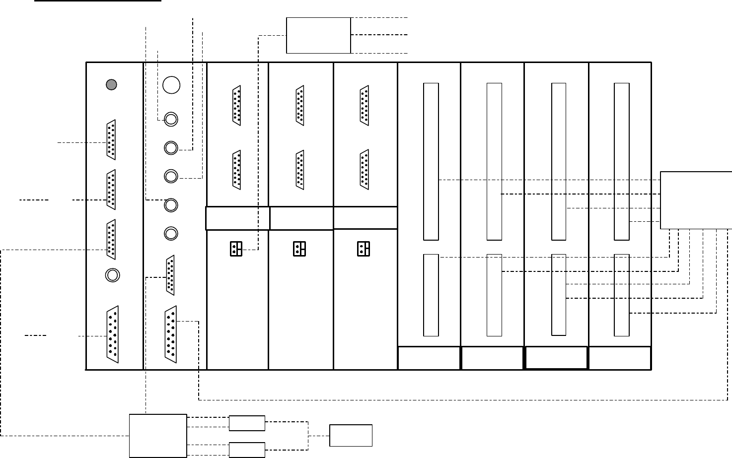
VME Rack Configuration
2/2
VME Rack Configuration
XP-241E
FH1001B
OUT PORT (GREEN LED)
IN PORT (RED LED)
SELECT/DISPLAY
FH1001B
OUT PORT (GREEN LED)
IN PORT (RED LED)
SELECT/DISPLAY
Run Reset
1
2
3
Mouse
IEEE8023
VIDEO IN
1
2
3
4
TRIG/STRB
RGB
I/O
GSV-2B
CN 2
CN 1
CN 3
GSV-2B
CN 2
CN 1
CN 3
GSV-2B
CN 2
CN 1
CN 3
FH1001B
OUT PORT (GREEN LED)
IN PORT (RED LED)
SELECT/DISPLAY
FH1001B
OUT PORT (GREEN LED)
IN PORT (RED LED)
SELECT/DISPLAY
CPU VISION
SERVO
SERVO
SERVO
I/O
I/OI/O I/O
Coplanarity
Camera
Mark
Camera
Parts
Camera 2
Parts
Camera 1
Strobe Power
Unit
Light Source Side 1
Light Source Side 2 A (Front Light)
Light Source Side 2 B (Side Light)
FH1138A0
(1PCB)
LCD1
LCD2
DC 12V
Touch Screen
Image
Y
X
Z
Q
U
T
EthernetPC
Main Terminal
PCB (M1PCB1)
Debug
Data
Connector
MCS2
FK-9F98-29 XP Series Training Text for Service Engineers
Edition 5.0 Supplementary Information
1/2
Basic Manual Optimizer for XP141E
Example: How to configure the nozzle set up for the following program, “Program X”.
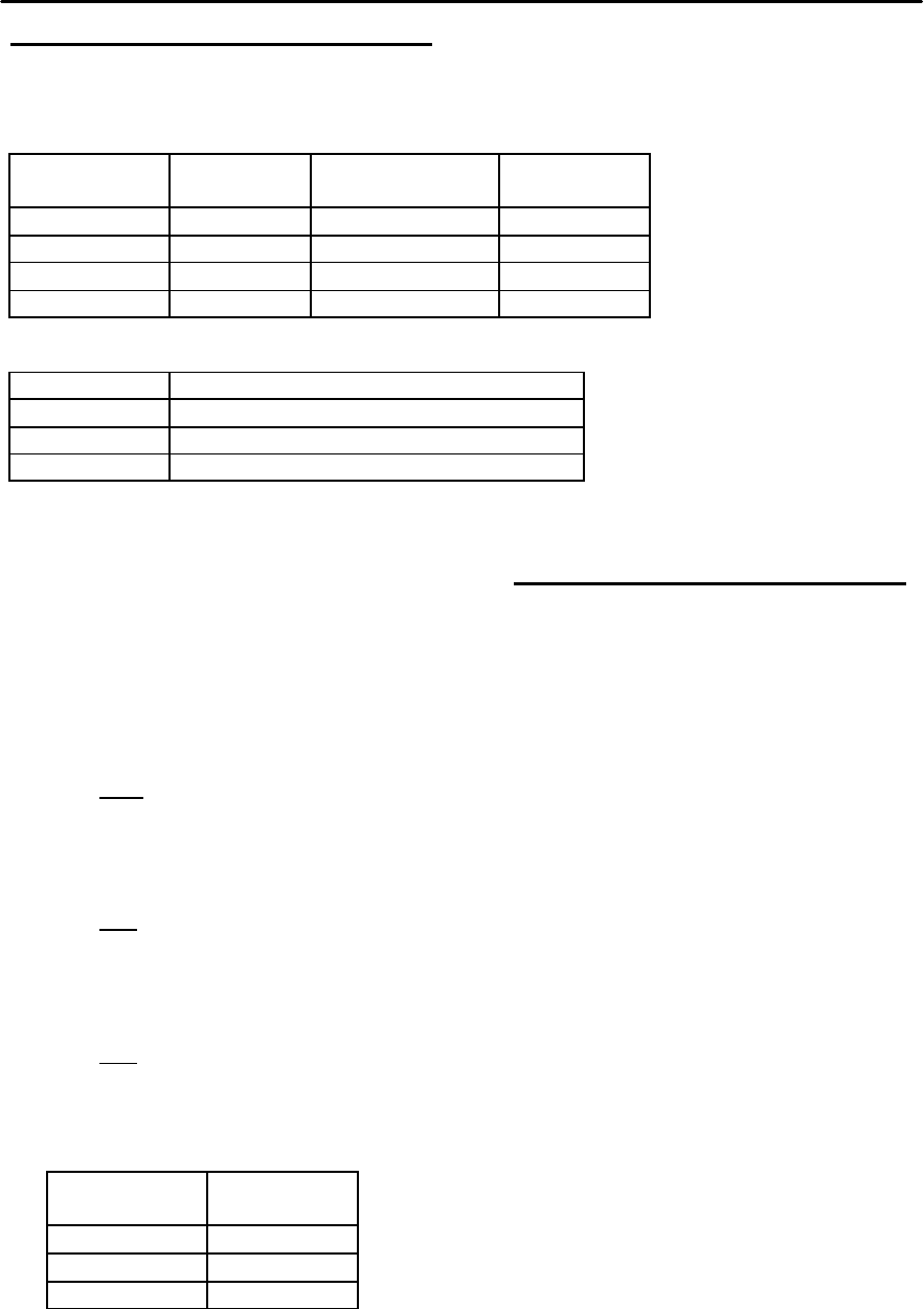
1.
Component Sequence Nozzle Size ø Sequence
Quantity
1005 1 ~ 20 0.7mm 20
1608 21 ~ 50 1.0mm 30
2125 51 ~ 80 1.3mm 30
3216 81 ~120 1.3mm 40
2.
Nozzle Type Sequence Quantity per Nozzle Type
0.7 20
1.0 30
1.3 70
3. To calculate the optimum nozzle configuration the following formula should be used:
(Number of nozzle slots on the revolver) X Seq. Quantity per Nozzle Type_____
Total number of seq. in the program
4. The formula above should be used to calculate the optimum number of nozzles for
each nozzle type.
5. Starting with the 0.7mm nozzle type:
12 X 20 = 2
120
6. Then the 1.0mm nozzle type:
12 X 30 = 3
120
7. And finally the 1.3mm nozzle type:
12 X 70 = 7
120
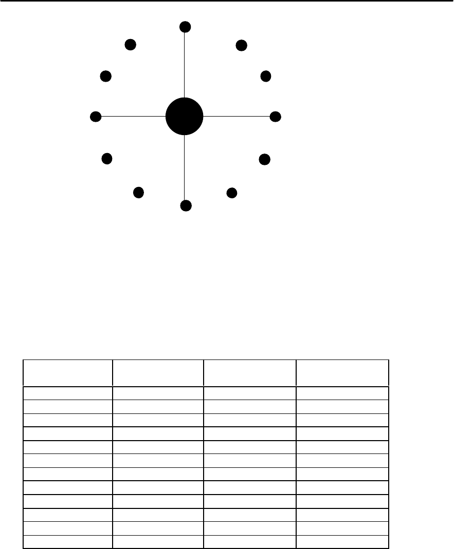
8. Thus for “Program X” the optimum nozzle configuration would be as follows:
Nozzle Type Number of
Nozzles
0.7mm 2
1.0mm 3
1.3mm 7
9. These should be arranged on the revolver as illustrated overleaf:
FK-9F98-29 XP Series Training Text for Service Engineers
Edition 5.0 Supplementary Information
2/2
10. If the nozzle configuration is optimized then the number of cycles will be kept to a
minimum regardless of the program sequence order.
11. The machine will not necessarily follow the sequence order input in the program
because this would mean a drastic increase in cycle time. If a nozzle is free it will be
used to place a part even if this means the part is placed out of sequence.
12. For example in the case of “Program X”, the first cycle of 12 placements would be as
follows:
Actual Seq.
Number
Nozzle Size Component Program Seq.
Number
1 0.7 1005 1
2 0.7 1005 2
3 1.0 1608 21
4 1.0 1608 22
5 1.0 1608 23
6 1.3 2125 51
7 1.3 2125 52
8 1.3 2125 53
9 1.3 2125 54
10 1.3 2125 55
11 1.3 2125 56
12 1.3 2125 57
13. If an error occurs the error sequence will be recovered once all the other sequences
have been placed.
14. It is difficult to optimize the feeder set up manually, however feeders should be
grouped as close together as possible in order to minimize the distance the pick
up/placing head has to travel between them.
0.7
0.7
1.0
1.0
1.0
1.3
1.3
1.3
1.3
1.3
1.3
1.3