xp141-241-341-5.0E.pdf - 第30页
FK-9F98- 29 XP Series Training Text for Service Engineers Edition 5.0 XP141 – Chapter 4 Loader Adjustment Page 5 of 12 Fuji Machine Mfg. Co., Ltd. Okazaki. SMT Equipment Quality Assurance Dept. 4 – 5 CS Section 8. Confir…
FK-9F98-29 XP Series Training Text for Service Engineers
Edition 5.0 XP141 – Chapter 4 Loader Adjustment Page 4 of 12
Fuji Machine Mfg. Co., Ltd. Okazaki.
SMT Equipment Quality Assurance Dept.
4 – 4 CS Section
5. Raise the main lifter. Under these conditions there should be no gap between the
clamper and the conveyor rail. If there is a gap it is necessary to adjust the stroke of the
main lifter cylinder (under the main table) until the board clamper contacts the underside
of the conveyor rail. Note that normally the stroke is already set and does not need to be
adjusted.
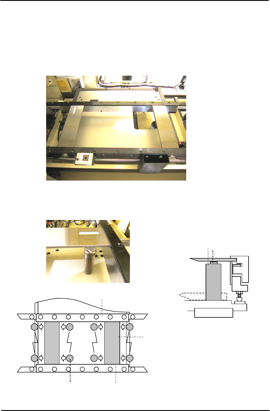
6. Clamp the two Lifter Height Adjustment Plate Jigs in the main table as shown in the
picture below:
7. Under these conditions re-adjust the board clamper adjustment bolts until surface C of
the Cylindrical Jig can slide in under the plate jigs as illustrated in the following pictures:
Each plate jig should be clamped 50mm from the end of
the main conveyor rail
Lifter Plate
C goes
through
D does not go
through
Movable
Rail
Plate Jig
Reference
Rail
Cylindrical Jig
Note that the back up plate
must be removed
FK-9F98-29 XP Series Training Text for Service Engineers
Edition 5.0 XP141 – Chapter 4 Loader Adjustment Page 5 of 12
Fuji Machine Mfg. Co., Ltd. Okazaki.
SMT Equipment Quality Assurance Dept.
4 – 5 CS Section
8. Confirm that surface C of the cylindrical jig can slide in under the plate jigs, and that
surface D of the cylindrical jig cannot.
9. Under these conditions confirm that both of the plate jigs are securely clamped and
cannot move.
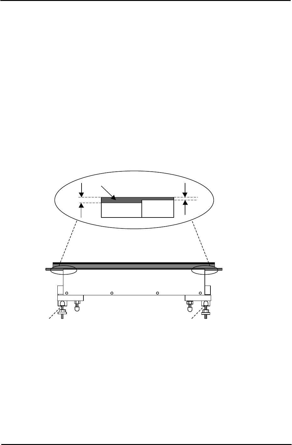
Main Table Lifter Plate Stoppers
In order to enhance the loading of panels on the XP series machines lifter plate stoppers
have been added. These keep the lifter plate parallel to the conveyor belt and in doing so
prevent the lifter plate from sticking at the upper limit position. To adjust the stoppers carry
out the following procedure:
1. Lower the lifter plate.
2. Adjust the position of the stoppers so that the lifter plate rests 0.5mm below the top
surface of the conveyor belt.
3. Refer to the diagram below and adjust the stoppers for both the fixed and adjustable rails:
Post Adjustment Checks:
1. Ensure that the clamper motion is smooth when the main table is raised and lowered.
2. Ensure there is sufficient clearance between the back-up pins and the under side of a
clamped board.
3. Confirm that the minimum (0.8mm) thick board and the maximum (4.0mm) board can be
clamped correctly.
Lifter Plate
Conveyor
Belt
0.5mm
1.0mm
Stopper Stopper
FK-9F98-29 XP Series Training Text for Service Engineers
Edition 5.0 XP141 – Chapter 4 Loader Adjustment Page 6 of 12
Fuji Machine Mfg. Co., Ltd. Okazaki.
SMT Equipment Quality Assurance Dept.
4 – 6 CS Section
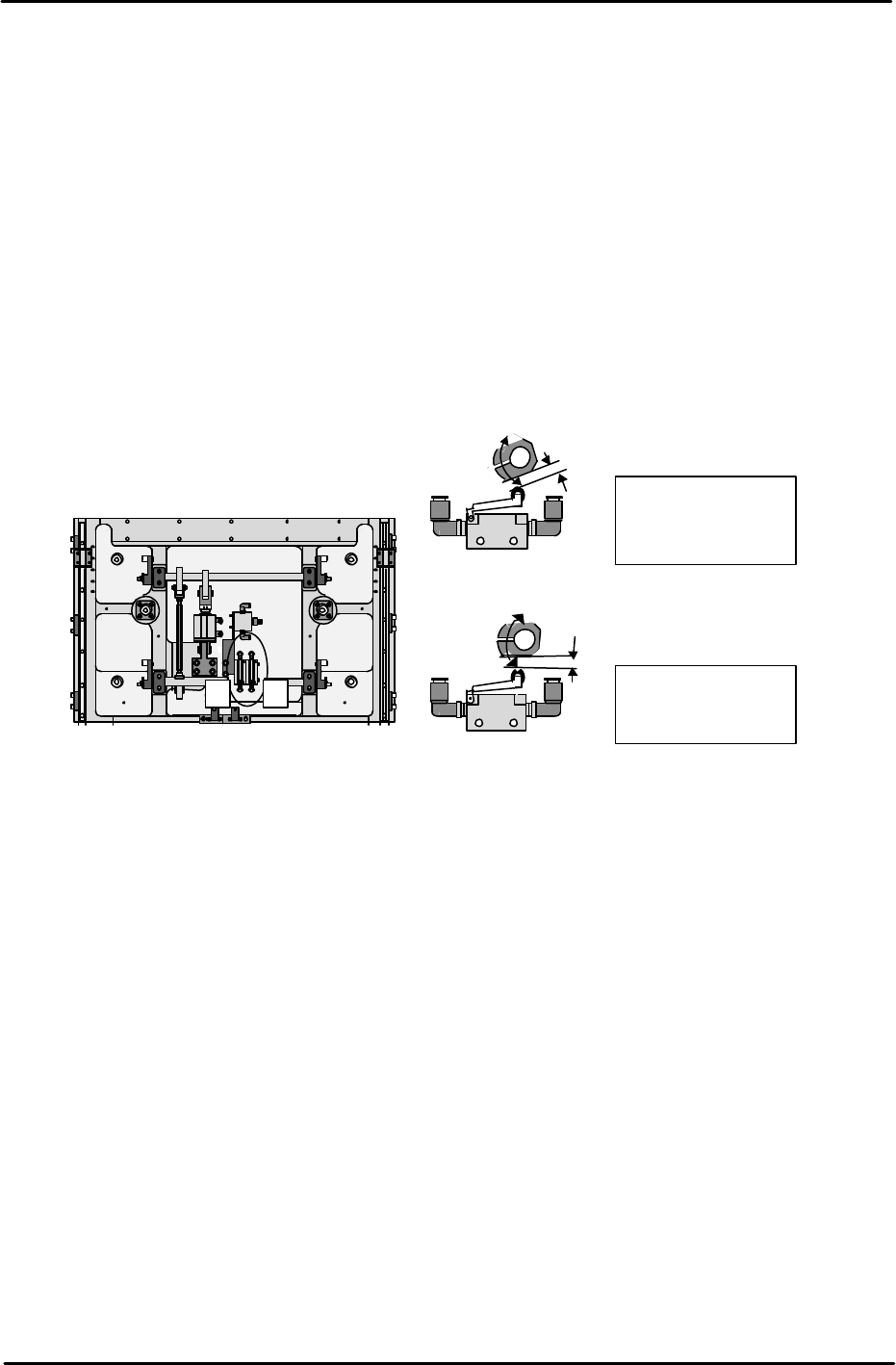
4.5 Main Table Pneumatic Switch Adjustment
Note: Before proceeding with these adjustments, confirm that the lifter plate flatness
check (4.1) is complete.
Fast Down Adjustment
1. With the lifter plate raised, adjust the position of the cam so that there is a gap of 1mm
between the cam and the pneumatic switch roller.
Fast Up Adjustment
2. With the lifter plate raised, adjust the position of the cam so that there is a gap of 3mm
between the cam and the pneumatic switch roller.
4.6 Lifter Upper/Lower Limit Sensor Adjustment
1. Raise the main lifter and adjust the flag so that the upper limit sensor turns ON when a
4mm thick board is clamped, and turns OFF when a 4.8mm thick board is clamped.
2. With the main lifter lowered, adjust the flag at the lower limit sensor side so that it is
positioned 1mm past the point where the sensor comes ON.
3. Ensure that the I/O X024 MainStLftUpChk is ON when the lifter is at its upper limit, and
X025 MainStLftDwnChk is ON when the lifter is at its lower limit.
4. Ensure that there is no vibration when the lifter is raised and lowered.
1
. Fast Down cam.
1mm gap with lifter
raised
2
. Fast UP cam.
Horizontal with lifter
raised
1
2
Machine rear under the lifter plate.
Machine front.