xp141-241-341-5.0E.pdf - 第35页
FK-9F98- 29 XP Series Training Text for Service Engineers Edition 5.0 XP141 – Chapter 4 Loader Adjustment Page 10 of 12 Fuji Machine Mfg. Co., Ltd. Okazaki. SMT Equipment Quality Assurance Dept. 4 – 10 CS Section 4.9 Boa…
FK-9F98-29 XP Series Training Text for Service Engineers
Edition 5.0 XP141 – Chapter 4 Loader Adjustment Page 9 of 12
Fuji Machine Mfg. Co., Ltd. Okazaki.
SMT Equipment Quality Assurance Dept.
4 – 9 CS Section
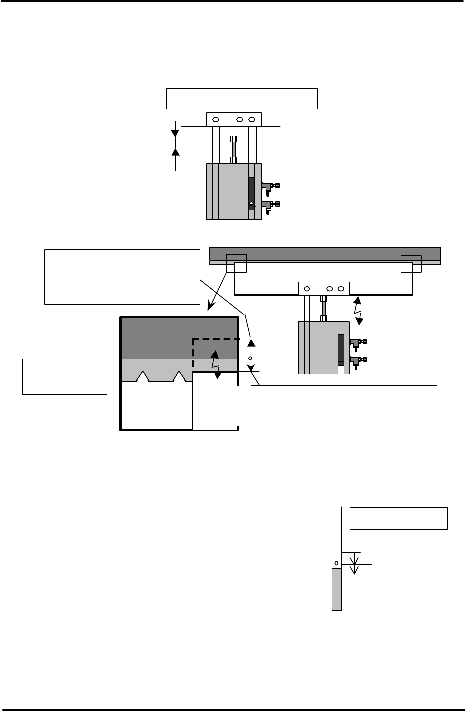
6. Turn I/O Y02D InStLifterUp OFF to lower the in-lifter. Ensure that the lifter plate top
surface is approx. 0.5mm below the conveyor belt top surface. Use a ruler to check.
Confirm both the height and tilt.
7. After adjustment is complete, place a board on the in-conveyor and raise the in-lifter.
Check that the board is not jolted up. And also ensure that the reference side/movable-
side up/down speed is balanced. If not, adjust using the cylinder speed controllers.
8. Air Cylinder Upper Limit Sensor
Turn I/O Y02D InStLifterUp ON and raise the in-lifter. Carry
out the upper limit sensor adjustment. (I/O X028
InStLftUpChk) Slowly raise the sensor from the lower
position until the sensor turns ON and keep raising until it
goes OFF. Then, lower the sensor until it comes ON and
fasten the sensor approximately 1mm below the point that it
first comes ON.
Top surface of
the conveyor belt
Ensure that when the plate is lowered, the
plate top surface is approximately 0.5mm
below the conveyor belt top surface.
When the plate is raised, the plate
top surface should be raised
approx. 1mm from the conveyor
belt top surface.
Lifter
Plate
Lifter Plate
Conveyor Belt
Adjust the clearance to 1.5mm.
Fix the sensor
Sensor ON: Lower 1mm
Sensor OFF
In-lifter (UP)
FK-9F98-29 XP Series Training Text for Service Engineers
Edition 5.0 XP141 – Chapter 4 Loader Adjustment Page 10 of 12
Fuji Machine Mfg. Co., Ltd. Okazaki.
SMT Equipment Quality Assurance Dept.
4 – 10 CS Section
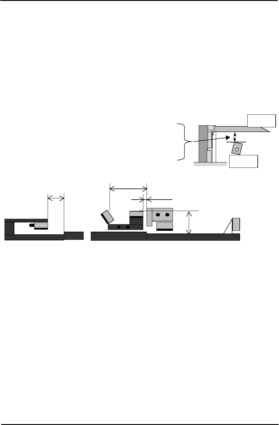
4.9 Board Sensors Adjustment
1. For each board sensor adjustment, use a FUJI96 board.
2. Set the sensor dial to its maximum volume (to clockwise).
Note: Ensure that when the sensor volume is at the maximum it does not detect any part
of the X and Y-axes moving above it. If the X or Y-axes affect the sensor, reduce the
sensor volume.
To ensure that there is enough clearance between the board and sensors, adjust the
distance between the board underside and the sensor top surface to the following
distances:
1. In-lifter board arrival sensor................................ X01B InStArrvChk
2. Main conveyor board deceleration sensor ......... X01C MainStDecelPnt
3. Main conveyor board arrival sensor.................... X01D MainStArrvChk
4. Main conveyor board pass sensor...................... X022 MainStPassChk
5. Out conveyor board pass sensor........................ X020 OutStPassChk
In- lifter board arrival sensor ............................27mm
Main conveyor board deceleration sensor.........25.5mm
Main conveyor board arrival sensor ................ 25.5mm
Main conveyor board pass sensor ...................30mm
Out conveyor board pass sensor ......................25.5mm
Board
Sensor
40mm
In-lifter
1
2 3
4
5mm
60mm
36mm
Main lifter
5
Out-conveyor
FK-9F98-29 XP Series Training Text for Service Engineers
Edition 5.0 XP141 – Chapter 4 Loader Adjustment Page 11 of 12
Fuji Machine Mfg. Co., Ltd. Okazaki.
SMT Equipment Quality Assurance Dept.
4 – 11 CS Section
4. 10 Conveyor Width and Movement
• Measuring tool: Calipers (0.05mm)
1. Ensure that the width change can be carried out smoothly, when the conveyor is moved
to its Min. (50mm or less) ~ Max. (356mm or greater) width.
Note: Do not use the conveyor auto width changer, as this is not adjusted yet.
2. Set the entrance of the In-conveyor to 130mm. Check a few points along the conveyor
width from entrance to exit. The difference between the maximum width and minimum
width should be within 0.5mm. If it is out of the tolerance, please contact FUJI.
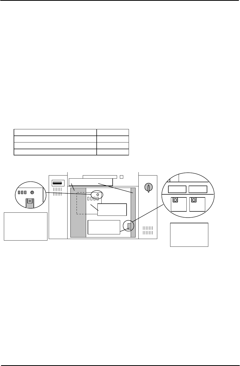
3. The speed of board loading and the speed of the conveyor width changer are set at FUJI
prior to machine shipment. Changing these speeds is not recommended. However for
your reference the location and function of the conveyor speed controllers are given
below:
Loading Function Controller
Board Loading (Normal speed) T1VR1
Board Loading (Deceleration) T1SP1
Conveyor width change T1SP2
T1SP1 T1SP2
Side1; Back of
the right door of
the bottom Box.
T1VR1
Side1: Rear of the
Electric Box, top
left connector on
the main relay
board.
Main relay
board
Speed control
board cover
Electric Box Door