xp141-241-341-5.0E.pdf - 第38页
C C h h a a p p t t e e r r 5 5 P P e e r r i i p p h h e e r r a a l l A A d d j j u u s s t t m m e e n n t t s s

FK-9F98-29 XP Series Training Text for Service Engineers
Edition 5.0 XP141 – Chapter 4 Loader Adjustment Page 12 of 12
Fuji Machine Mfg. Co., Ltd. Okazaki.
SMT Equipment Quality Assurance Dept.
4 – 12 CS Section
NOTES:

C
C
h
h
a
a
p
p
t
t
e
e
r
r
5
5
P
P
e
e
r
r
i
i
p
p
h
h
e
e
r
r
a
a
l
l
A
A
d
d
j
j
u
u
s
s
t
t
m
m
e
e
n
n
t
t
s
s
FK-9F98-29 XP Series Training Text for Service Engineers
Edition 5.0 XP141 – Chapter 5 Peripheral Adjustments Page 1 of 16
Fuji Machine Mfg. Co., Ltd. Okazaki
SMT Equipment Quality Assurance Dept.
5 – 1 CS Section
Chapter 5 – Peripheral Adjustments
5.1 Adjusting the MFU
The following calibrations should be performed for all MFUs and at both sides of the
machine.
MFU height adjustment
1. Equipment: MFU device jig (Z9631ADEPJ10000). 2 lever type dial gages (0.002mm).
2. Adjust the MFU air valve speed controllers as described in the following table:
Speed controller location Number of turns from fully closed Function
Upper speed controller 2 turns from fully closed Unclamp
Lower speed controller 1.5 turns from fully closed Clamp
3. Confirm that there is no jolting when clamping and unclamping the MFU. If necessary
make slight adjustments to the speed controllers to achieve smooth clamping and
unclamping.
4. Clamp the MFU.
Warning: the MFU device table is very heavy; please take extreme care to prevent
your finger/hand getting caught when carrying out height or other adjustments on
the MFU.
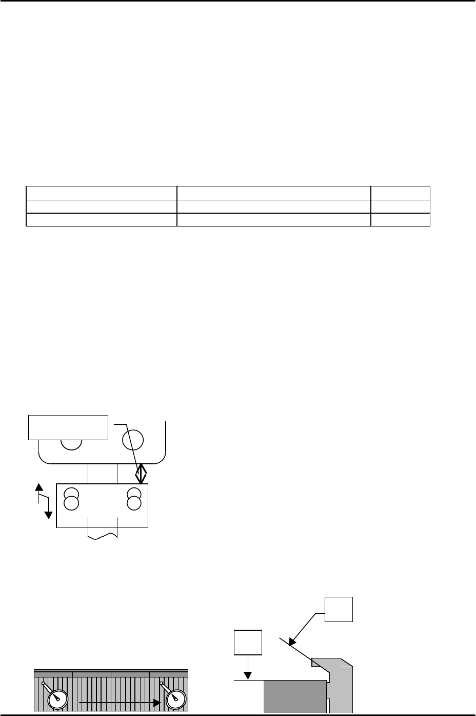
5. Adjust the MFU height adjustment stopper, so that when the MFU is clamped, the gap
between the stopper and the MFU device table underside is approximately 20mm.
Please see the following diagram:
MFU device table measurement
1. Use a dial gage to measure device surfaces A and B. Please refer to the diagram below:
Approx. 20mm
Tolerance: 0.05mm /
A
B
0
D1
D50