xp141-241-341-5.0E.pdf - 第41页
FK-9F98- 29 XP Series Training Text for Service Engineers Edition 5.0 XP141 – Chapter 5 Peripheral Adjustments Page 3 of 16 Fuji Machine Mfg. Co., Ltd. Okazaki SMT Equipment Quality Assurance Dept. 5 – 3 CS Section 3. Se…
FK-9F98-29 XP Series Training Text for Service Engineers
Edition 5.0 XP141 – Chapter 5 Peripheral Adjustments Page 2 of 16
Fuji Machine Mfg. Co., Ltd. Okazaki
SMT Equipment Quality Assurance Dept.
5 – 2 CS Section
2. Tolerance is 0.05mm/800mm.
3. Measure the second MFU and any additional MFUs in the same manner.
MFU Y and Z direction static accuracy
1. Choose one MFU as the reference and clamp it at side 1.
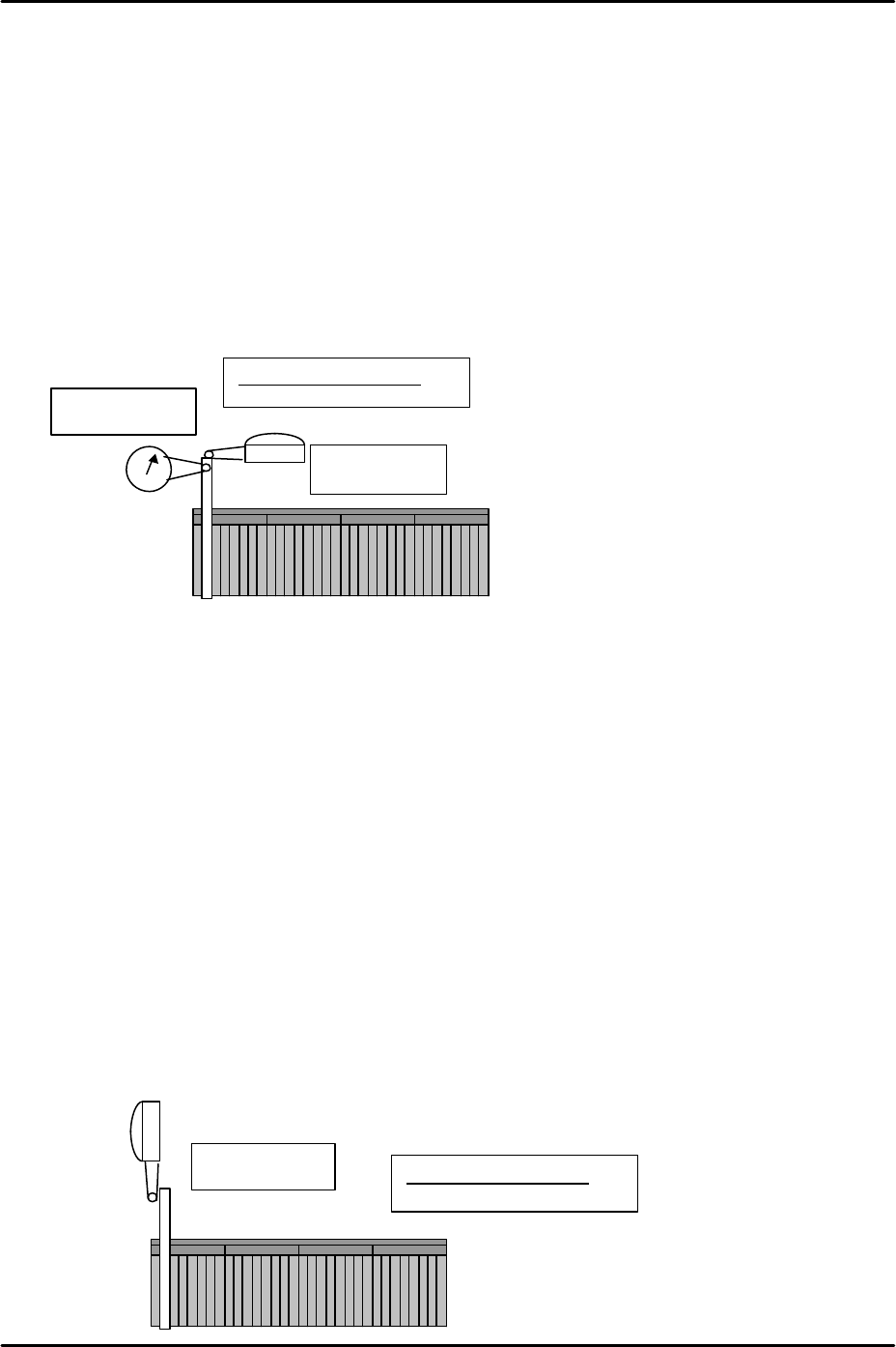
2. Mount the device jig in slot No. 2 and use an extension bar to attach the two dial gages to
the placement head.
3. Put the tip of the dial gages against the end of the device jig in the Y and the Z directions.
Please refer to the following illustration:
4. Set the dial gages to 0 and jog the head away from the device jig in the X direction.
Record the current Y-axis counter value and then unclamp the MFU.
5. In place of the reference MFU clamp the second MFU or any additional MFUs at side 1.
6. Mount the device jig in slot No. 2 and turn the servo power ON. Ensure the Y counter
value is the same as that recorded in step 4 and then jog the head in the X direction until
the dial gages contact the device jig in the Y and Z directions.
7. Check the difference between the reference MFU and the second (or additional MFUs) in
the Z and Y directions. Tolerance is +/- 0.035mm. If out of tolerance please contact
FUJI.
MFU X direction static accuracy
1. Clamp the reference MFU used in previous steps to side 1.
2. Mount the device jig in slot No.2 and set the dial gage tip against the jig in the X direction.
Please refer to the illustration below:
Z-direction
Y-direction
Tolerance:
±
0.035mm
X-direction
Tolerance: ±0.035mm
FK-9F98-29 XP Series Training Text for Service Engineers
Edition 5.0 XP141 – Chapter 5 Peripheral Adjustments Page 3 of 16
Fuji Machine Mfg. Co., Ltd. Okazaki
SMT Equipment Quality Assurance Dept.
5 – 3 CS Section
3. Set the dial to 0 and then jog the head in the Y direction to slide the dial gage tip away
from the jig.
4. Record the current X-axis servo counter value and then unclamp the MFU.
5. Clamp the second MFU (or any additional MFUs) and mount the device jig in slot No.2
and turn the servo ON.
6. Ensure the X axis counter value is the same as that recorded in step 4 and then jog the
head in the Y direction until the dial gage tip contacts the jig.
7. Check the difference between the reference MFU and the second MFU (or any additional
MFUs) in the X-direction. Tolerance is +/- 0.035mm.
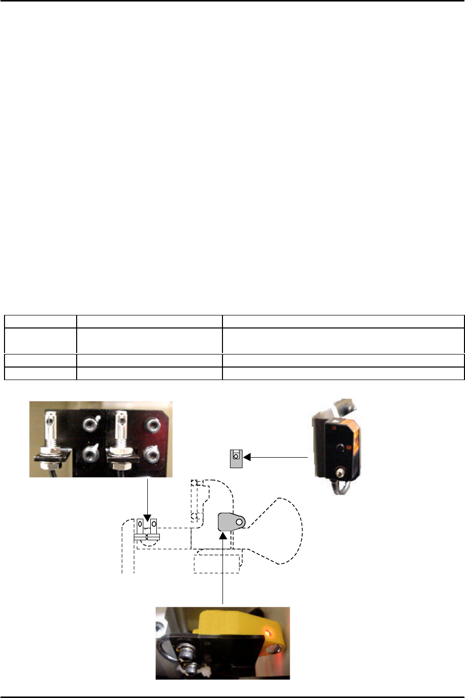
5. 2 MFU tape leaf and feeder check sensor adjustments
There are three different types of MFU tape leaf check and feeder check sensors. Check the
sensor type prior to this adjustment.
The following photos show the sensors on machines shipped after September 2002 (X 94 or
higher). Refer to the table below for details of the sensor manufacturer and function.
Sensor No. Function Manufacturer
1 Tape leaf detection sensor Yamatake fiber type. Fiber: HPF-T003.
Attachment: FE-PA-S1
2 Interlock sensor Yamatake LED type: HPJ-T23
3 Feeder set check sensor Schmersl LED type: SLB 200-R(E)31-32
1
2
3
FK-9F98-29 XP Series Training Text for Service Engineers
Edition 5.0 XP141 – Chapter 5 Peripheral Adjustments Page 4 of 16
Fuji Machine Mfg. Co., Ltd. Okazaki
SMT Equipment Quality Assurance Dept.
5 – 4 CS Section
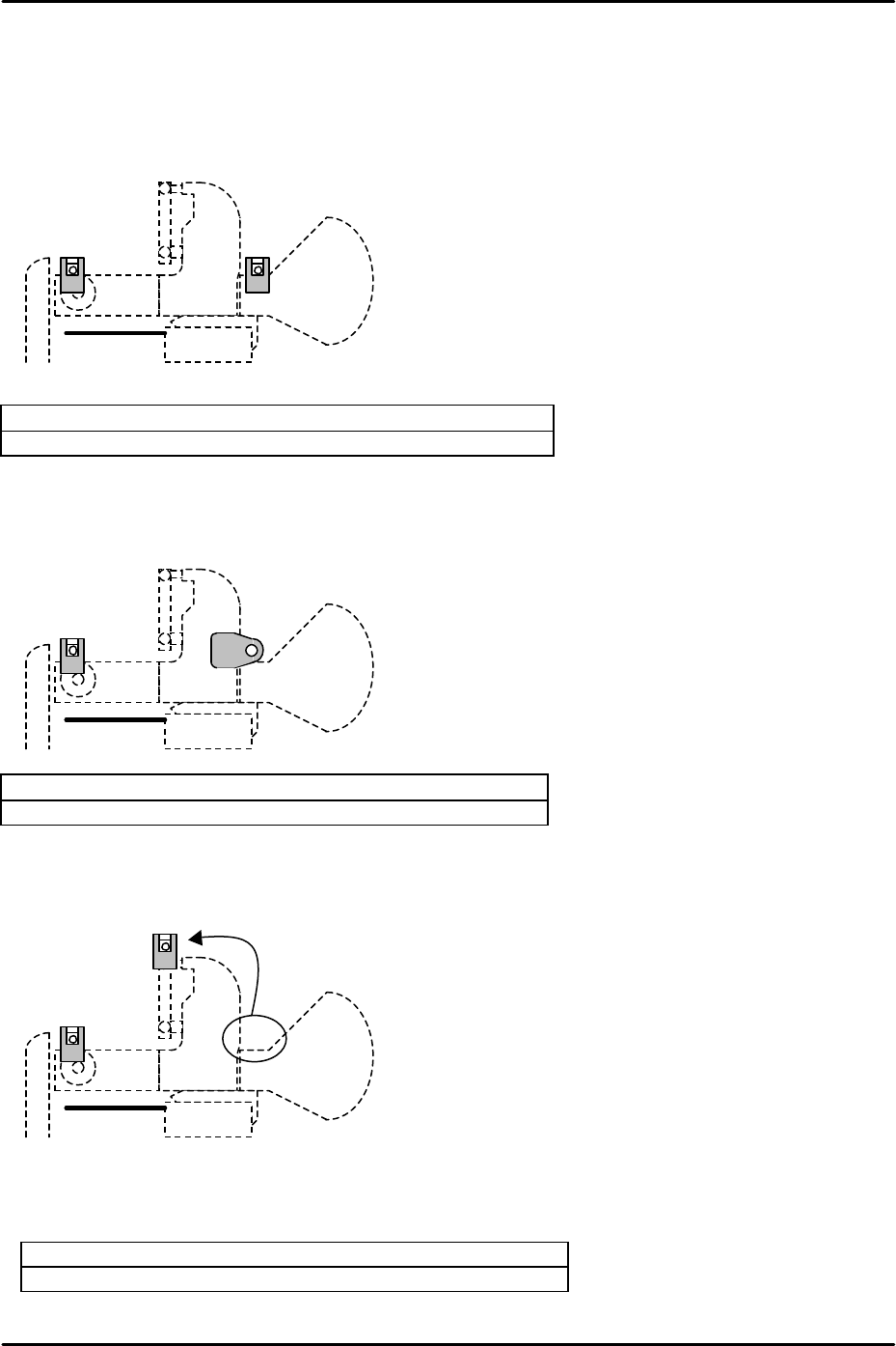
Currently there are 5 different types of tape leaf/feeder check sensor configuration on XP1.
The type of configuration depends on the specification of the machine and the date of
shipment. The 5 different configurations are as follows:
Configuration A (Xno.93 or earlier)
Feeder tape leaf detection sensor: Yamatake LED type
Feeder set check sensor: Yamatake LED type
Configuration B (EC type Xno.94 or later)
Feeder tape leaf detection sensor: Yamatake LED type
Feeder set check sensor: Schmersl LED type
Configuration C (AA mode machines)
To enable MFU detachment during production the feeder set check sensor has been moved
and the beam functions as an interlock in the feeder indexing lever area.
Feeder tape leaf detection sensor: Yamatake LED type
Feeder set check sensor: Yamatake LED type