xp141-241-341-5.0E.pdf - 第46页
FK-9F98- 29 XP Series Training Text for Service Engineers Edition 5.0 XP141 – Chapter 5 Peripheral Adjustments Page 8 of 16 Fuji Machine Mfg. Co., Ltd. Okazaki SMT Equipment Quality Assurance Dept. 5 – 8 CS Section Adjus…
FK-9F98-29 XP Series Training Text for Service Engineers
Edition 5.0 XP141 – Chapter 5 Peripheral Adjustments Page 7 of 16
Fuji Machine Mfg. Co., Ltd. Okazaki
SMT Equipment Quality Assurance Dept.
5 – 7 CS Section
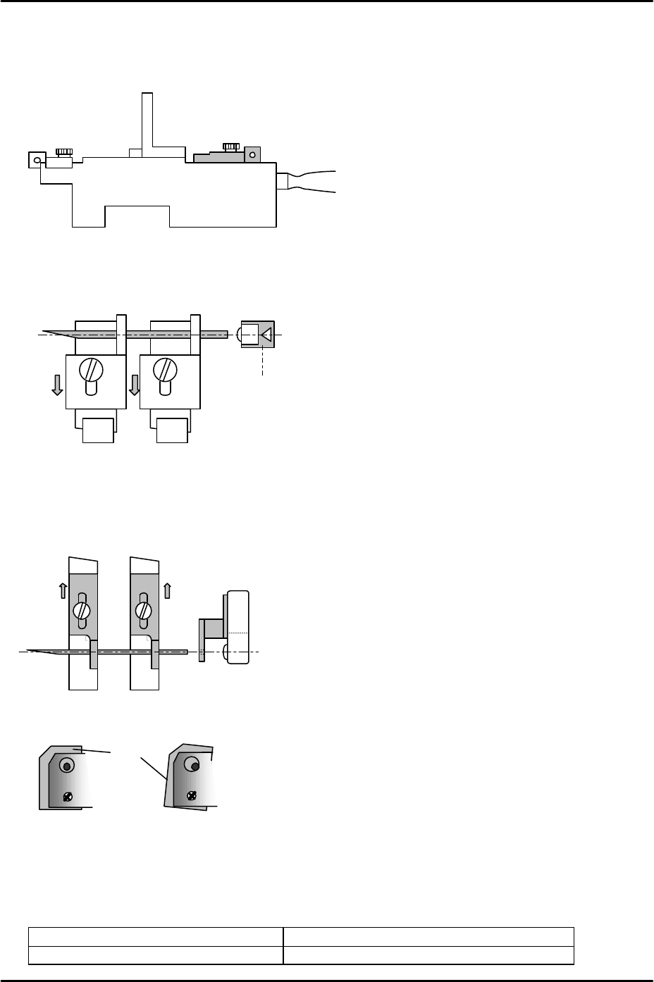
Adjustment for configuration B
1. Clamp the MFU and load two EC type feeder sensor adjustment jigs (Z9631ADEPJ8040)
at slots D47 and D49.
2. Fix the front sliding attachments at their backward limit (in the direction away from the
machine interior) and insert a 1.8mm diameter wire jig between the holes in the
attachments. Adjust the tape leaf check sensor position so that the point where the
sensor beam is emitted is aligned with the center of the wire jig.
3. Fix the sliding attachments for the Schmersl sensor at their forward limit (in the direction
towards the machine interior) and insert a 1.8mm diameter wire jig between the holes in
the attachments. Adjust the feeder set check sensor position so that the point where the
sensor beam is emitted is aligned with the center of the wire jig.
4. Check the tilt of both sensors:
5. Move the feeder sensor jigs to D2 and D4 and repeat steps 2 to 4 for the sensors at the
left side of the MFU.
6. Finally check the operation of both sets of sensors by I/O.
Feeder set check sensor FH1000_1: [X017] Side 1 XY Axis Inter
Feeder tape leaf detection sensor FH1000_2: [X02C] Side1 FdeDetect
D49D47
Tape leaf check sensor
D49
D47
Z9631ADEPJ8040
Sensor
BKT
BKT
FK-9F98-29 XP Series Training Text for Service Engineers
Edition 5.0 XP141 – Chapter 5 Peripheral Adjustments Page 8 of 16
Fuji Machine Mfg. Co., Ltd. Okazaki
SMT Equipment Quality Assurance Dept.
5 – 8 CS Section
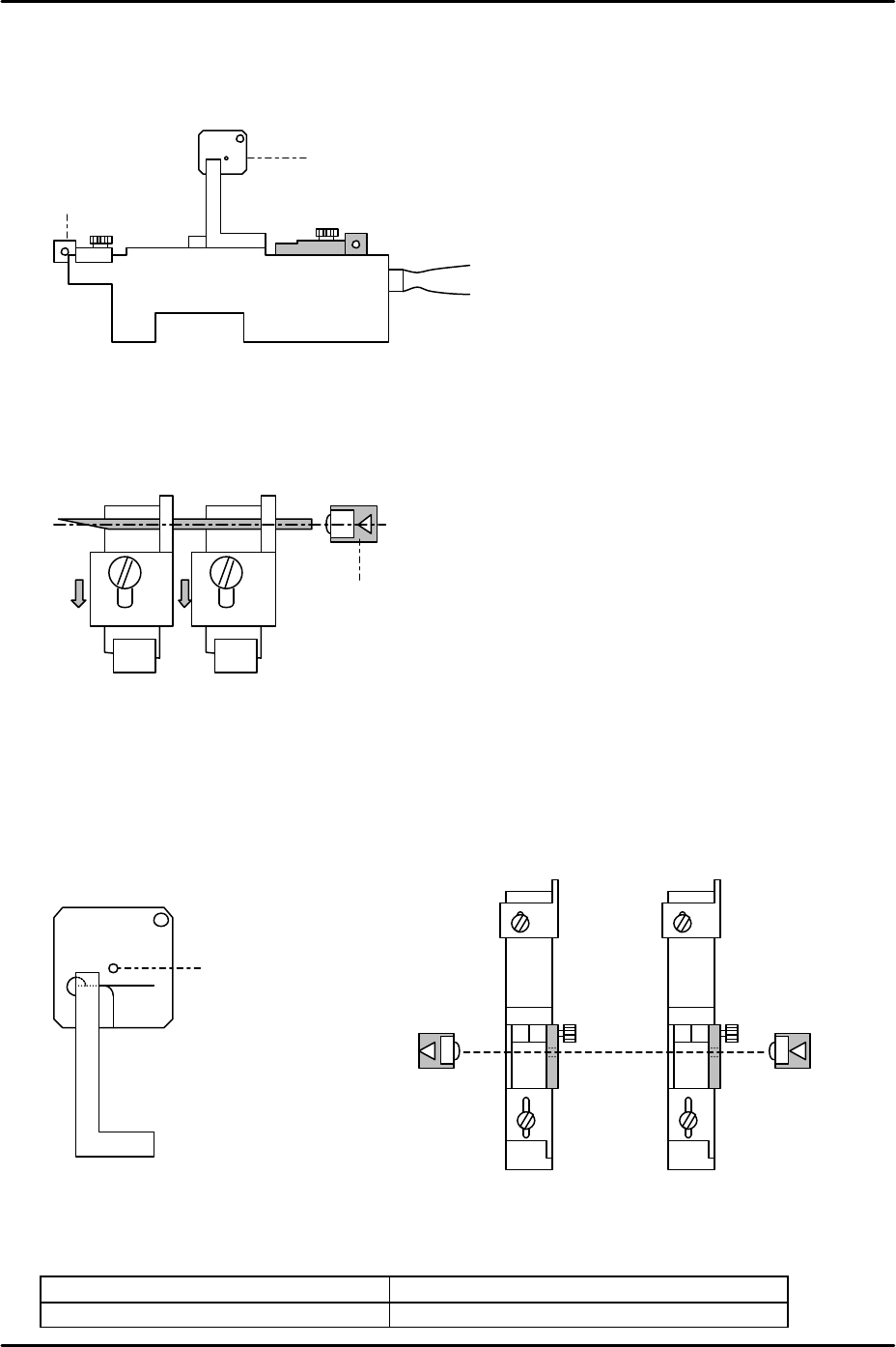
Adjustment for configuration C
1. Clamp the MFU and load two EC type feeder sensor adjustment jigs
(Z9631ADEPJ8040) at slots D47 and D49 at side 1.
2. Fix the front sliding attachments at their backward limit (in the direction away from the
machine interior) and insert a 1.8mm diameter wire jig between the holes in the
attachments. Adjust the tape leaf check sensor position so that the point where the
sensor beam is emitted is aligned with the center of the wire jig.
3. Move the two feeder sensor adjustment jigs to slots D2 and D4 and then repeat step 2
for the tape leaf check sensor on the left side of the MFU.
4. Load two EC type feeder sensor adjustment jigs (with AA-mode feeder set check sensor
position adjustment jig plates attached) at D2 and D49 at side 1. Adjust the position of
the feeder set check sensor transmitter and receiver so that the light beam goes through
the holes in the attachment plates. Use I/O X017 to monitor the signal.
5. Check the tilt of the sensors and confirm they are not triggered by the XY robot.
6. Finally check the operation of both sets of sensor by I/O.
Feeder set check sensor FH1000_1: [X017] Side 1 XY Axis Inter
Feeder tape leaf detection sensor FH1000_2: [X02C] Side1 FdeDetect
AA mode feeder set check
sensor position adjustment jig
plate
D49D47
Tape leaf check sensor
Hole in
attachment
plate
Z9631ADEPJ8040
Front sliding
attachment
FK-9F98-29 XP Series Training Text for Service Engineers
Edition 5.0 XP141 – Chapter 5 Peripheral Adjustments Page 9 of 16
Fuji Machine Mfg. Co., Ltd. Okazaki
SMT Equipment Quality Assurance Dept.
5 – 9 CS Section
Adjustment for configurations DA and DB (double detection type)
For details of how to adjust the feeder set check sensors for configurations DA and DB, refer
to the adjustment procedures for configurations A and B. The adjustment procedure
described below is for the “double detection type” tape leaf sensor only.
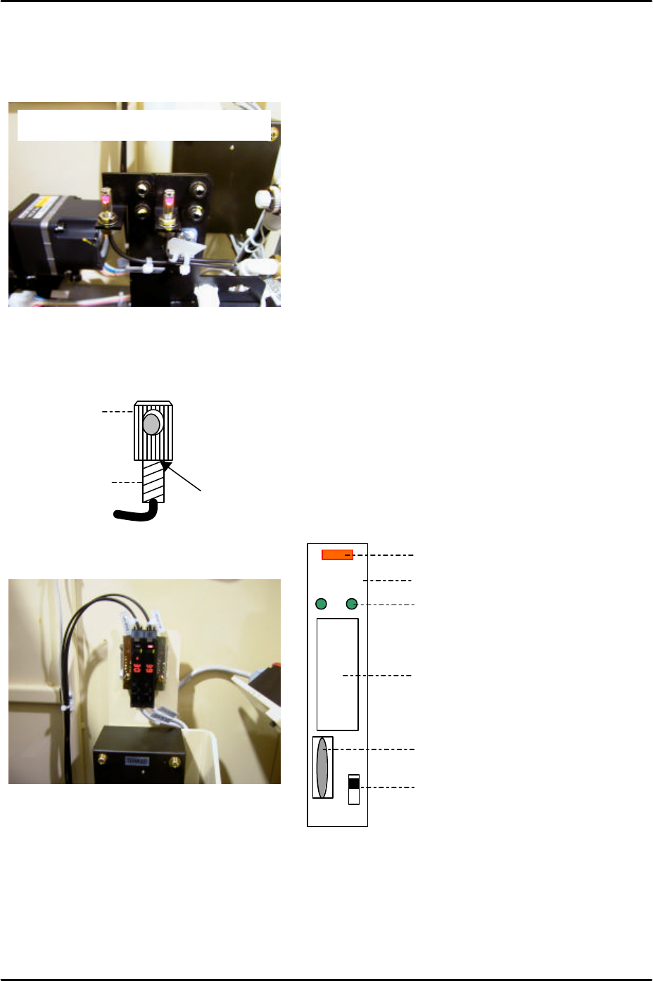
Initial setting
1. Fix the attachment to the fiber sensor using Loctite 222 adhesive.
Amplifier frequency setting
1. Set the L-ON/D-ON changeover switch to L_ON.
2. Press the dial switch once (the RUN light in the Mode Display flashes and “AA” is
displayed on the digital display).
3. Turn the dial switch until SET flashes on the “Mode Display”.
LO DO
RUN
SET
TMR
ADJ
Digital Display
Operation Light
L-ON/D-ON Changeover Switch
Dial Switch
Mode Display
Mode Lights
Double detection type tape leaf sensors
Attachment
Fiber sensor
Apply Loctite 222 here