xp141-241-341-5.0E.pdf - 第53页
FK-9F98- 29 XP Series Training Text for Service Engineers Edition 5.0 XP141 – Chapter 5 Peripheral Adjustments Page 15 of 16 Fuji Machine Mfg. Co., Ltd. Okazaki SMT Equipment Quality Assurance Dept. 5 – 15 CS Section 5.5…

FK-9F98-29 XP Series Training Text for Service Engineers
Edition 5.0 XP141 – Chapter 5 Peripheral Adjustments Page 14 of 16
Fuji Machine Mfg. Co., Ltd. Okazaki
SMT Equipment Quality Assurance Dept.
5 – 14 CS Section
5.4 Adjusting the waste tape cutter
WARNING: the waste tape cutter plate is an extremely heavy item. Please handle with
care. Also, take extreme caution when handling (or working in the vicinity of) the
cutter blade. It may cause damage or personal injury.
1. Remove the MFU, and the waste tape cutter cover.
2. For the waste tape cutter cylinder air valve speed controller adjustments please refer to
the following table:
Speed controller Air Tube Line Number of turns from fully closed
Cutter close valve U5 7.5
Cutter open valve U6 8
3. Repeat the procedure for the side 2 cutter.
Cutter engagement adjustment
1. Disconnect the air supply to the machine and pull out the two air tubes that supply air to
the tape cutter cylinder. This will allow you to operate the tape cutter manually.
2. Ensure the gap between the movable cutter topside and the fixed cutter underside is
within 0 to 0.03mm when both cutters are engaged.
3. Ensure there are no nicks or cracks in the cutter blade.
4. Repeat the procedure for the side 2 cutter.
Stopper position adjustment
1. Loosen the stopper and position it just at the end of the cylinder stroke.
2. Lock the stopper 1.5 to 2.0mm in from this position.
3. This procedure should be carried out for both the cutter close stopper and the cutter open
stopper.
4. Repeat the procedure for the side 2 cutter.
Retract limit sensor adjustment
1. With the stopper adjustment complete, adjust the side 1 retract limit sensor so that when
the cutter is moved to its retract limit the I/O (Y031 Side1TpCutOrgPos) comes ON
1.5mm in from the cylinder stroke end.
2. Repeat the procedure for the side 2 cutter (Y033 Side2TpCutOrgPos).
FK-9F98-29 XP Series Training Text for Service Engineers
Edition 5.0 XP141 – Chapter 5 Peripheral Adjustments Page 15 of 16
Fuji Machine Mfg. Co., Ltd. Okazaki
SMT Equipment Quality Assurance Dept.
5 – 15 CS Section
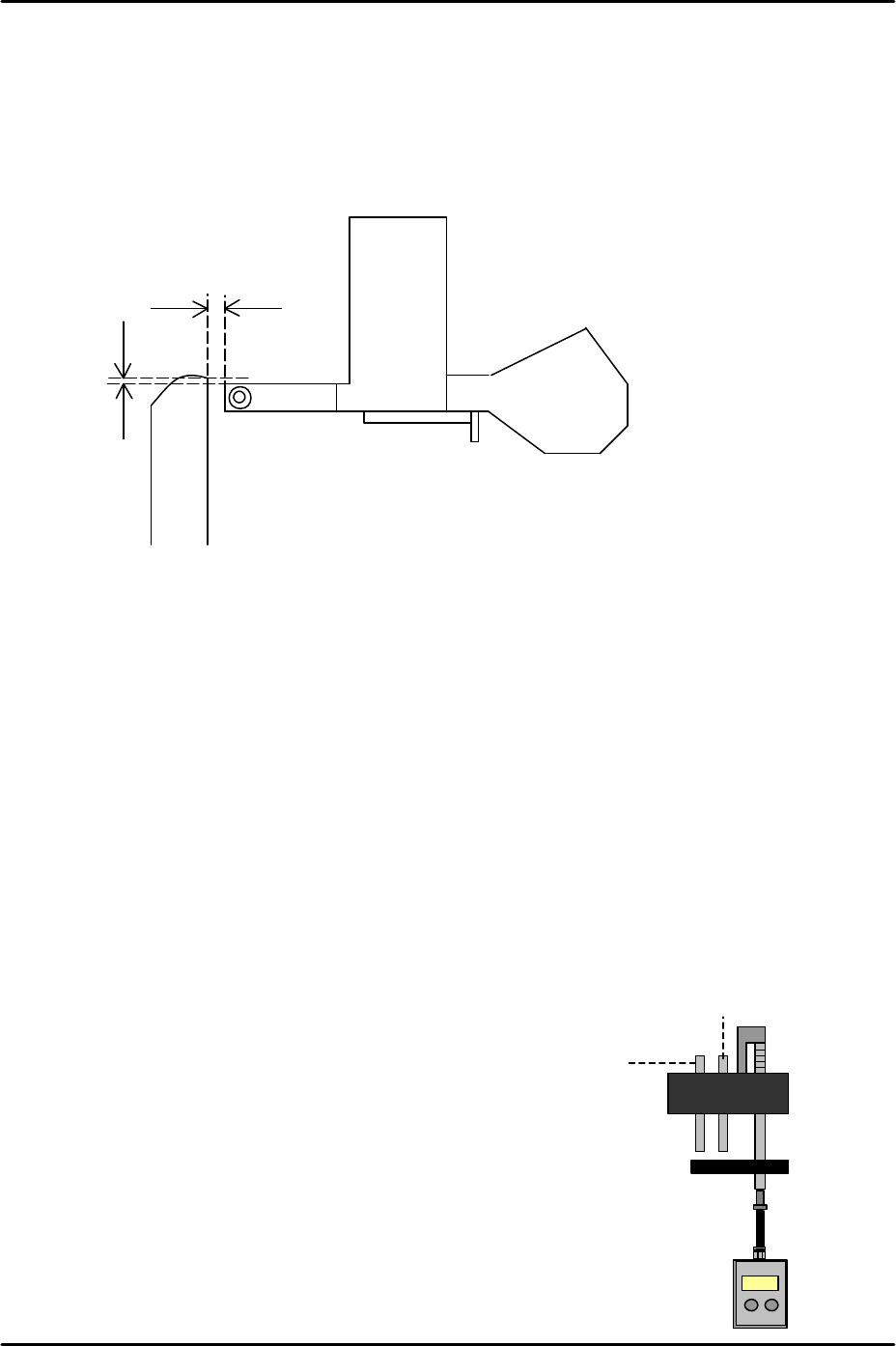
5.5 Waste tape duct height adjustment
1. Clamp the MFU and insert feeders in slots number 2 and 49.
2. Set the height of the waste tape duct approximately 1mm higher than the top of the
feeder so that there is sufficient clearance for the waste tape to feed down the duct into
the waste tape box.
3. Set the waste tape duct 1.5 to 3.5mm from the tape feeder end in the Y-direction. Please
refer to the diagram above.
5.6 Measuring the vacuum pressure
1. Equipment: manometer. Nozzle and air tube.
Vacuum pressure check
1. Select [Maintenance A] – [I/O Check] – [Y01F ResetCylinder] – [ON] to raise the parts
vacuum pin and the air blow pin.
2. Select [Maintenance A] – [I/O check] – [Y01F ResetCylinder] – [OFF] to lower the reset
cylinder.
3. Attach the nozzle and air tube at nozzle
position 1.
4. Press the nozzle No.1 vacuum pin down.
5. Select [Maintenance A] – [I/O Check] – [Y016
VacuumPump] – [ON] and check the vacuum
pressure reading on the manometer.
6. The reading should be –600 mmHg (-79.99
kPa) or more negative.
1.5 to 3.5mm
Approx. 1mm
Vacuum pin
Air blow pin
FK-9F98-29 XP Series Training Text for Service Engineers
Edition 5.0 XP141 – Chapter 5 Peripheral Adjustments Page 16 of 16
Fuji Machine Mfg. Co., Ltd. Okazaki
SMT Equipment Quality Assurance Dept.
5 – 16 CS Section
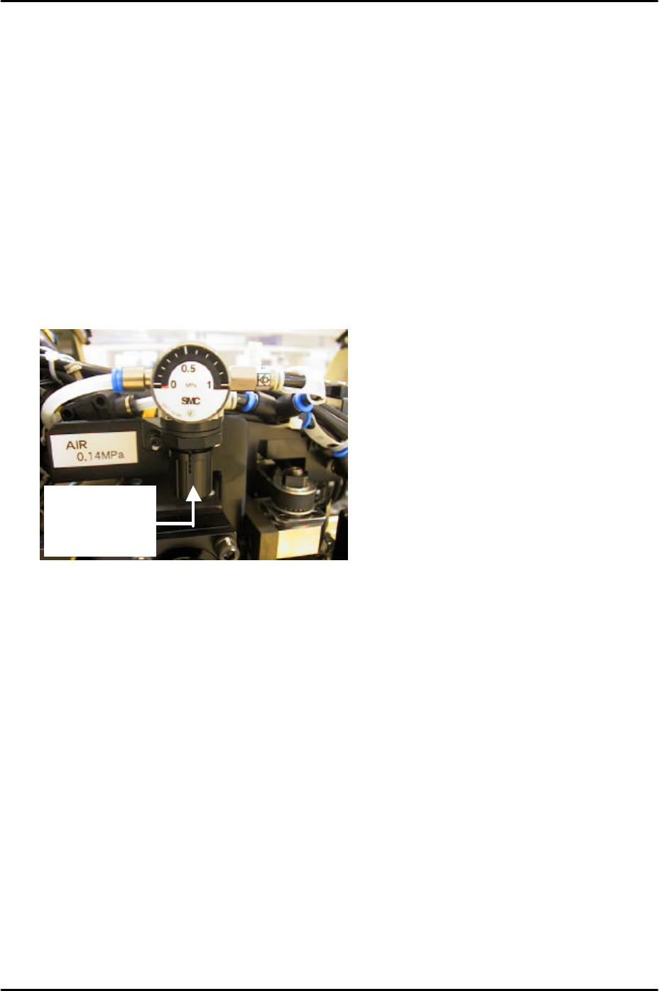
Air blow pressure check
1. Select [Maintenance A] – [I/O Check] – [Y01F ResetCylinder] – [ON] to raise the parts
vacuum pin and the air blow pin.
2. Select [Maintenance A] – [I/O check] – [Y01F ResetCylinder] – [OFF] to lower the reset
cylinder.
3. Attach the nozzle and air tube at nozzle position 1.
4. Push down the vacuum pin and the air blow pin.
5. Select [Maintenance A] – [I/O check] – [Y016 VacuumPump] – [ON] and [Y01D
partspickUpDes] – [ON] and check the air blow pressure. Adjust the air regulator on top
of the placement head until the pressure reading is 110 +/- 10 mmHg (14.67 +/- 1.33
kPa).
To adjust pull
down and
turn.