xp141-241-341-5.0E.pdf - 第55页
C C h h a a p p t t e e r r 6 6 P P r r o o p p e e r r D D a a t t a a M M e e a a s s u u r r e e m m e e n n t t s s
FK-9F98-29 XP Series Training Text for Service Engineers
Edition 5.0 XP141 – Chapter 5 Peripheral Adjustments Page 16 of 16
Fuji Machine Mfg. Co., Ltd. Okazaki
SMT Equipment Quality Assurance Dept.
5 – 16 CS Section
Air blow pressure check
1. Select [Maintenance A] – [I/O Check] – [Y01F ResetCylinder] – [ON] to raise the parts
vacuum pin and the air blow pin.
2. Select [Maintenance A] – [I/O check] – [Y01F ResetCylinder] – [OFF] to lower the reset
cylinder.
3. Attach the nozzle and air tube at nozzle position 1.
4. Push down the vacuum pin and the air blow pin.
5. Select [Maintenance A] – [I/O check] – [Y016 VacuumPump] – [ON] and [Y01D
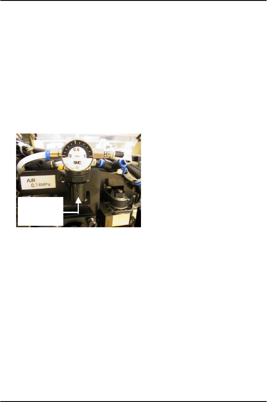
partspickUpDes] – [ON] and check the air blow pressure. Adjust the air regulator on top
of the placement head until the pressure reading is 110 +/- 10 mmHg (14.67 +/- 1.33
kPa).
To adjust pull
down and
turn.

C
C
h
h
a
a
p
p
t
t
e
e
r
r
6
6
P
P
r
r
o
o
p
p
e
e
r
r
D
D
a
a
t
t
a
a
M
M
e
e
a
a
s
s
u
u
r
r
e
e
m
m
e
e
n
n
t
t
s
s
FK-9F98-29 XP Series Training Text for Service Engineers
Edition 5.0 XP141 – Chapter 6 Proper Data Measurements Page 1 of 26
Fuji Machine Mfg. Co., Ltd. Okazaki
SMT Equipment Quality Assurance Dept.
6 – 1 CS Section
Chapter 6 – Proper data measurements
6.1 Prism adjustment
1. Equipment: dial gage (0.01mm).
2. The following adjustments should be performed manually with the emergency stop button
pressed, and the 200-volt power supply to the servos OFF.
3. Remove the light source unit from the side 1 prism.
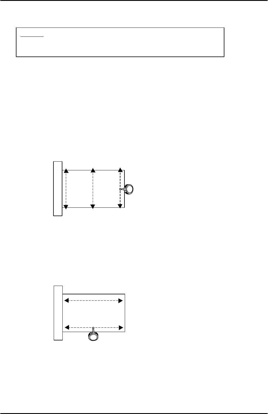
4. Use an extension bar to attach the dial gage to the placement head and measure the
flatness in the Y-direction as indicated by the arrows in the following diagram:
5. The flatness of the prism in the Y-direction should be within 0.01mm. If not, loosen the 4
bolts attaching the prism bracket to the X-axis and adjust the Y-direction tilt of the prism
so that the flatness comes within tolerance.
6. Having set the flatness within tolerance in the Y-direction it is necessary to check the
flatness in the X-direction as indicated by the arrows in the following diagram:
7. Set the dial gage tip on the prism top surface and then carefully move the X-axis so that
the dial tip moves across the prism surface.
8. The flatness of the prism in the X-direction should be within 0.01mm. The X-direction
flatness is not adjustable so if it is outside of tolerance please contact FUJI.
9. Repeat the procedure for the side 2 prism.
View of prism top
surface from above
View of prism top
surface from above
Caution:
The cameras may be unstable immediately after the machine
power is turned ON. Perform mark and parts camera adjustments at
least 10 minutes after turning the machine power ON.