xp141-241-341-5.0E.pdf - 第57页
FK-9F98- 29 XP Series Training Text for Service Engineers Edition 5.0 XP141 – Chapter 6 Proper Data Measurements Page 2 of 26 Fuji Machine Mfg. Co., Ltd. Okazaki SMT Equipment Quality Assurance Dept. 6 – 2 CS Section 6.2…
FK-9F98-29 XP Series Training Text for Service Engineers
Edition 5.0 XP141 – Chapter 6 Proper Data Measurements Page 1 of 26
Fuji Machine Mfg. Co., Ltd. Okazaki
SMT Equipment Quality Assurance Dept.
6 – 1 CS Section
Chapter 6 – Proper data measurements
6.1 Prism adjustment
1. Equipment: dial gage (0.01mm).
2. The following adjustments should be performed manually with the emergency stop button
pressed, and the 200-volt power supply to the servos OFF.
3. Remove the light source unit from the side 1 prism.
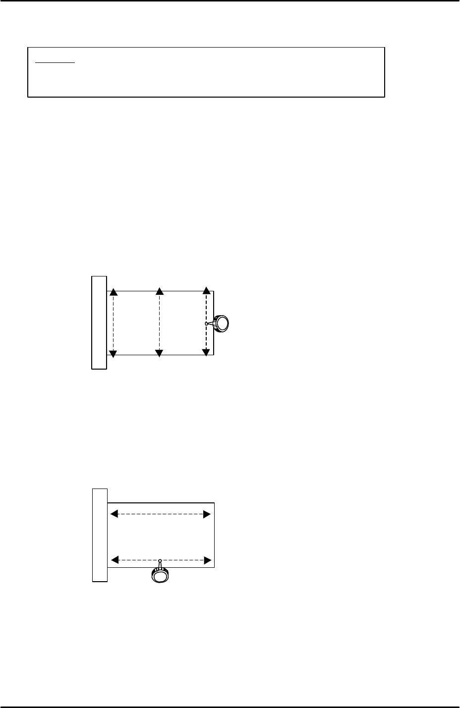
4. Use an extension bar to attach the dial gage to the placement head and measure the
flatness in the Y-direction as indicated by the arrows in the following diagram:
5. The flatness of the prism in the Y-direction should be within 0.01mm. If not, loosen the 4
bolts attaching the prism bracket to the X-axis and adjust the Y-direction tilt of the prism
so that the flatness comes within tolerance.
6. Having set the flatness within tolerance in the Y-direction it is necessary to check the
flatness in the X-direction as indicated by the arrows in the following diagram:
7. Set the dial gage tip on the prism top surface and then carefully move the X-axis so that
the dial tip moves across the prism surface.
8. The flatness of the prism in the X-direction should be within 0.01mm. The X-direction
flatness is not adjustable so if it is outside of tolerance please contact FUJI.
9. Repeat the procedure for the side 2 prism.
View of prism top
surface from above
View of prism top
surface from above
Caution:
The cameras may be unstable immediately after the machine
power is turned ON. Perform mark and parts camera adjustments at
least 10 minutes after turning the machine power ON.
FK-9F98-29 XP Series Training Text for Service Engineers
Edition 5.0 XP141 – Chapter 6 Proper Data Measurements Page 2 of 26
Fuji Machine Mfg. Co., Ltd. Okazaki
SMT Equipment Quality Assurance Dept.
6 – 2 CS Section
6.2 Parts camera adjustment
Settings
1. If attaching the camera to the camera installation bracket, 0.5N.m torque force should be
used to tighten the bolts.
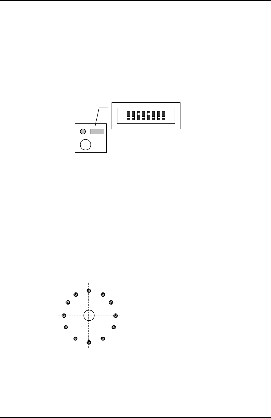
2. Set the parts camera aperture to 4, lock the aperture ring hollow bolt, and apply adhesive
(Loctite 425).
3. On the top of the camera turn the No.3 and No.5 dip switches ON, and check that all the
remaining dipswitches are OFF.
4. The join where the lens unit and camera are connected should be reinforced with
adhesive (Loctite 425).
5. After the settings are complete install the camera in the machine.
Camera centering
1. Install 1.8mm nozzles in all twelve nozzle positions on the revolver.
2. Select [Maintenance A] – [Jog] – [Side1] to activate the side 1 prism light source and
display the parts camera live image.
3. Move the revolver above the side 1 prism and display the cross hairs on the screen.
4. Set the revolver center in the center of the horizontal cross hair by sliding the camera in
the Y-direction.
5. Set the revolver center in the center of the vertical cross hair by sliding the camera in the
X-direction.
6. Select [Side2] to activate the side2 prism light source and inch the revolver above the
side 2 prism.
Vertical crosshair
Horizontal crosshair
FK-9F98-29 XP Series Training Text for Service Engineers
Edition 5.0 XP141 – Chapter 6 Proper Data Measurements Page 3 of 26
Fuji Machine Mfg. Co., Ltd. Okazaki
SMT Equipment Quality Assurance Dept.
6 – 3 CS Section
7. Check that the cross hairs are in the center of the revolver.
8. When the cross hairs are not in the center of the revolver carry out the following
procedure.
9. To set the revolver center in the center of the horizontal cross hair, slide the side 2 prism
in the Y direction.
10. If the revolver center is misaligned with the vertical cross hair then compare the vertical
alignment of the revolver at the side 1 prism with the vertical alignment at the side 2
prism, then slide the camera in the X-direction to even out the misalignment between the
two, please see the example below:
11. If at any time the side 1 prism or side 2 prism have been moved it is necessary to
recheck the prism flatness (see 6.1 Prism adjustment).
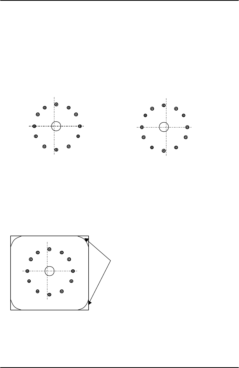
12. Once the camera has been aligned with the two prisms and the prism flatness confirmed,
bring the revolver above each prism in turn and inch the Y axis until the revolver is
directly above the center of the prism light source unit, please refer to the illustration
below:
13. Record the Y-axis counter value at this position and then select [Maintenance C] –
[Proper Data Editor] – [Prizm Position] – [PrismFront] or [PrismBack] and manually input
the counter value.
Side 1 Prism
Side 2 Prism
To tell if the revolver is directly above the center of the
prism light source unit check in the corners of the
image where the boundary of the light source unit is
visible. The boundary in the top corners of the image
should be balanced with the boundary in the bottom
corners of the image.