xp141-241-341-5.0E.pdf - 第61页
FK-9F98- 29 XP Series Training Text for Service Engineers Edition 5.0 XP141 – Chapter 6 Proper Data Measurements Page 6 of 26 Fuji Machine Mfg. Co., Ltd. Okazaki SMT Equipment Quality Assurance Dept. 6 – 6 CS Section 8. …
FK-9F98-29 XP Series Training Text for Service Engineers
Edition 5.0 XP141 – Chapter 6 Proper Data Measurements Page 5 of 26
Fuji Machine Mfg. Co., Ltd. Okazaki
SMT Equipment Quality Assurance Dept.
6 – 5 CS Section
4. Place the color sample disc (grey color side facing downwards) on the nozzles.
5. Select [Maintenance A] – [Jog] – [Side1] to activate the side1 prism light source and
display the parts camera live image on the screen.
6. Bring the color sample disc above the Side1 prism and press the image on the screen to
display a brightness reading.
7. The brightness readings will vary somewhat depending on which part of the color sample
disc image is touched. Set the average brightness level to 120 +/- 10 by adjusting the
parts camera gain.
8. Bring the color sample disc above the Side2 prism and confirm that the brightness
reading is within tolerance for the Side2 prism as well.
9. If the brightness level is too bright even with the brightness gain at minimum, then contact
FUJI.
6.5 Parts camera resolution measurement
1. Equipment: resolution measurement jig (Z3502DEAJ0020).
2. Put 1.8mm diameter nozzles in all twelve of the nozzle slots.
3. Select [Maintenance A] – [I/O Check] – [Y016 VacuumPump] – [ON].
4. Lower all of the vacuum pins, but leave the air blow pins at their upper limit.
5. Remove the half mirror from the light source unit.
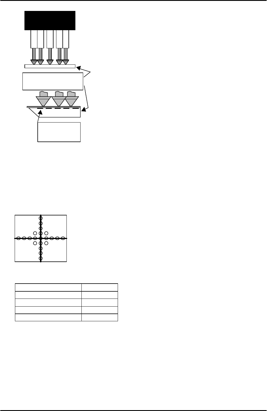
6. Attach the resolution jig to the nozzles.
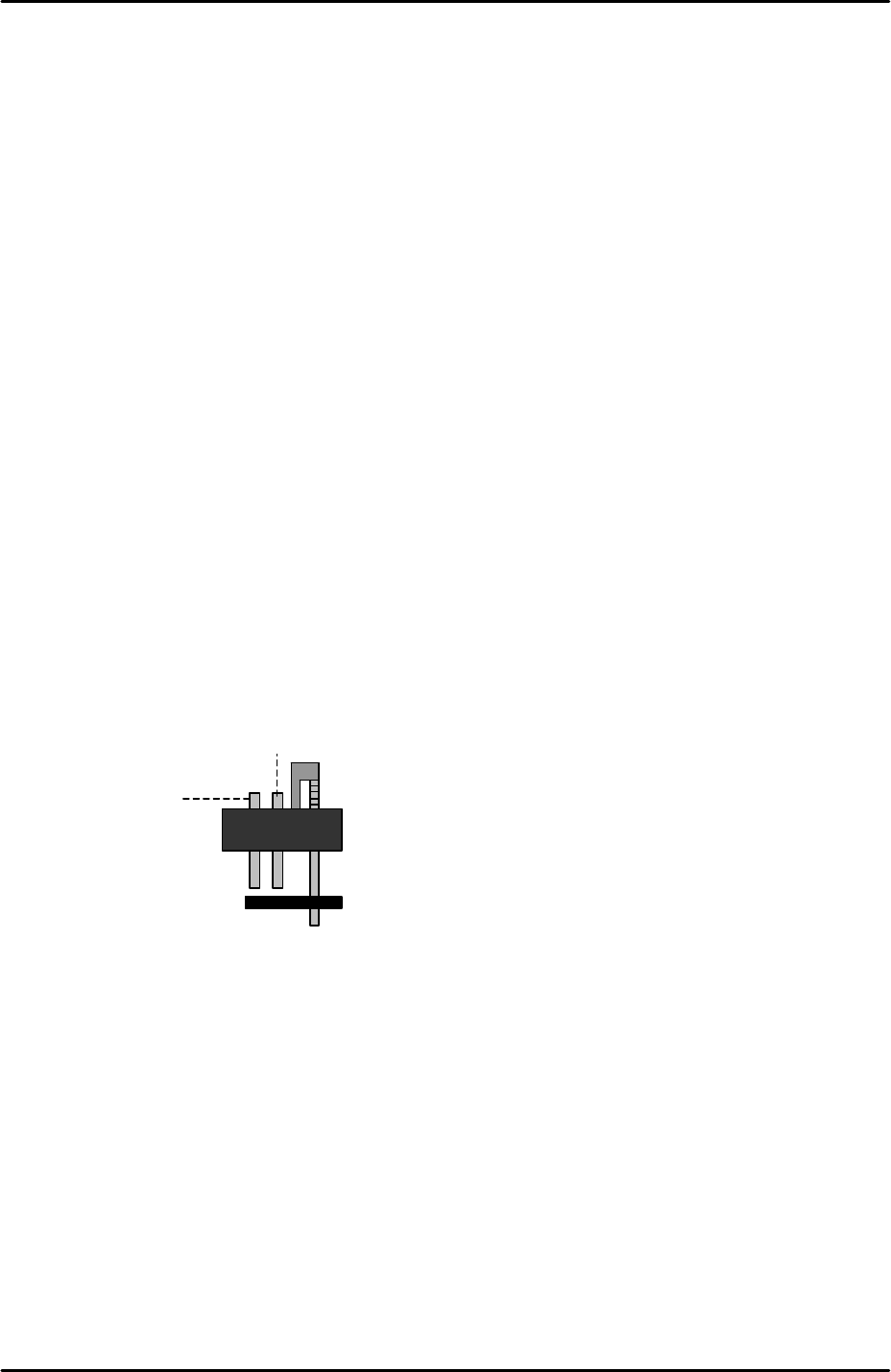
7. Note that the two sides of the resolution measurement gage are not identical. The glass
gage should be attached to the nozzles with the printed surface uppermost:
Vacuum pin
Air blow pin
FK-9F98-29 XP Series Training Text for Service Engineers
Edition 5.0 XP141 – Chapter 6 Proper Data Measurements Page 6 of 26
Fuji Machine Mfg. Co., Ltd. Okazaki
SMT Equipment Quality Assurance Dept.
6 – 6 CS Section
8. Inch the Y-axis to the “PrismFront” position (see 6.2 “camera centering” steps 12 and 13).
9. Select [Maintenance A] – [Jog] – [Side1] to activate the side1 prism light source and
display the parts camera live image on the screen.
10. Select the cross hairs and then adjust the position of the resolution measurement jig until
the center dot is in the center of the camera cross hairs:
11. Select [Maintenance A] – [I/O Check] – and turn the following I/Os ON:
I/O Signal
Y00C StroboTrigger ON
Y00D StroboLampA ON
Y00E StroboLampB ON
Y00F StroboCharge ON
12. Select [Program] – [Template Editor] – and then right click on the screen to display a
menu box.
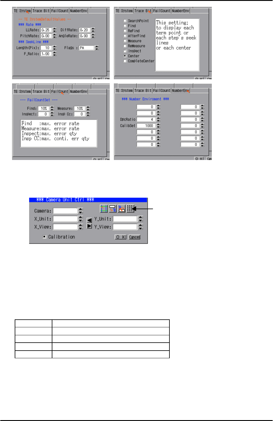
13. Select [Utility] – [Default Setting] and confirm that the default settings are identical to
those shown below, note that the default settings are the same for the parts camera and
the mark camera:
Resolution measurement
glass gauge.
Printed surface
uppermost
FK-9F98-29 XP Series Training Text for Service Engineers
Edition 5.0 XP141 – Chapter 6 Proper Data Measurements Page 7 of 26
Fuji Machine Mfg. Co., Ltd. Okazaki
SMT Equipment Quality Assurance Dept.
6 – 7 CS Section
14. Select [Utility] – [Scale Setting] – [Camera 1] – and click on the resolution measurement
tab:
15. Answer YES to the question “Set Center?” and the resolution measurement will proceed.
16. Answer NO to the question “Do you save calibration data to FD?”
17. To the next question “Save calibration data?” answer YES.
18. Confirm that the resolution results are within the tolerances described below:
Parts camera resolution tolerances
X_Unit 0.0280 ~ 0.032
X_View 38.800 ~ 44.198
Y_Unit 0.0280 ~ 0.032
Y_View 28.985 ~ 33.015
19. The resolution measurement is now complete, right click on the screen and select
[Return].
Resolution
Measurement
1