xp141-241-341-5.0E.pdf - 第64页
FK-9F98- 29 XP Series Training Text for Service Engineers Edition 5.0 XP141 – Chapter 6 Proper Data Measurements Page 9 of 26 Fuji Machine Mfg. Co., Ltd. Okazaki SMT Equipment Quality Assurance Dept. 6 – 9 CS Section Mar…
FK-9F98-29 XP Series Training Text for Service Engineers
Edition 5.0 XP141 – Chapter 6 Proper Data Measurements Page 8 of 26
Fuji Machine Mfg. Co., Ltd. Okazaki
SMT Equipment Quality Assurance Dept.
6 – 8 CS Section
6.6 Adjusting the mark camera
1. Equipment: color sample disc for brightness measurement (Z9531DEPJ1111). Plate Jig
(AJPJ – 0060).
(XC-55) Mark camera setting
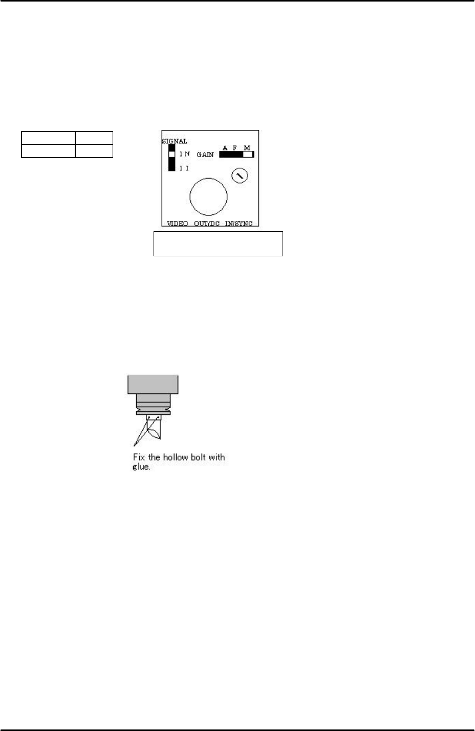
1. Set the mark camera settings as outlined in the following table and diagram:
Signal 1N
Gain M
2. If attaching the mark camera unit to the mark camera installation bracket use 0.5N.m
torque.
3. Ensure that the join where the camera lens unit and camera are connected is reinforced
with adhesive.
4. Ensure that adhesive (ThreeBond 1530C) is applied to the hollow bolts that hold the half
mirror in place. Do not over apply adhesive.
Mark camera focus
1. Clamp the plate jig in the main conveyor.
2. Select [Maintenance A] – [Jog] – [Fiducial] – the light comes ON for the mark camera and
the live image is displayed on the screen.
3. Inch the mark camera over the plate jig and set the focus by loosening the mark camera
bracket height adjusting bolts, and then sliding the camera up and down until the
optimum focus height is found.
4. Finally lock the mark camera bracket height adjusting bolts.
Top view of the camera
The orientation of the half-mirror is
not critical to the mark camera
operation; therefore any orientation
is acceptable.
FK-9F98-29 XP Series Training Text for Service Engineers
Edition 5.0 XP141 – Chapter 6 Proper Data Measurements Page 9 of 26
Fuji Machine Mfg. Co., Ltd. Okazaki
SMT Equipment Quality Assurance Dept.
6 – 9 CS Section
Mark camera brightness measurement
1. Clamp the plate jig in the main conveyor.
2. Place the color sample disc on top of the plate jig.
3. Select [Maintenance A] – [Jog] – [Fiducial] – the light comes ON for the mark camera and
the live image is displayed on the screen.
4. Inch the mark camera above the color sample disc and touch the image on the screen. A
brightness value will appear.
5. Set the brightness value to 130 +/- 10 by turning the gain adjusting screw on top of the
mark camera.
6. The brightness value will vary slightly at different points on the color sample image,
therefore set the average value to 130.
6.7 Measuring the mark camera resolution
1. Equipment: mark camera resolution measurement jig (Z3502DEAJ0020).
2. Clamp the resolution jig in the main conveyor. It should be flush with the reference rail,
and the printed surface should be uppermost.
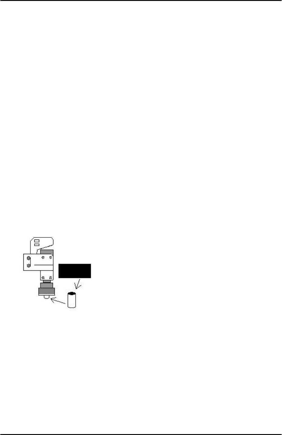
3. Insert a rolled up piece of black cardboard inside the mark camera light source. This acts
as a shade to reduce the light intensity during the resolution measurement:
4. Select [Maintenance A] – [Jog] – [Fiducial] – the fiducial lamp comes ON and the mark
camera live image is displayed on the screen.
5. Inch the mark camera over the center of the resolution jig.
6. Select the cross hairs and set the center of the cross hairs in the center of the resolution
jig center dot.
7. Select [Maintenance A] – [I/O Check] – [Y010 fiducial lamp] – ON.
8. Select [Program] – [Template Editor] and right click on the screen to display a menu box.
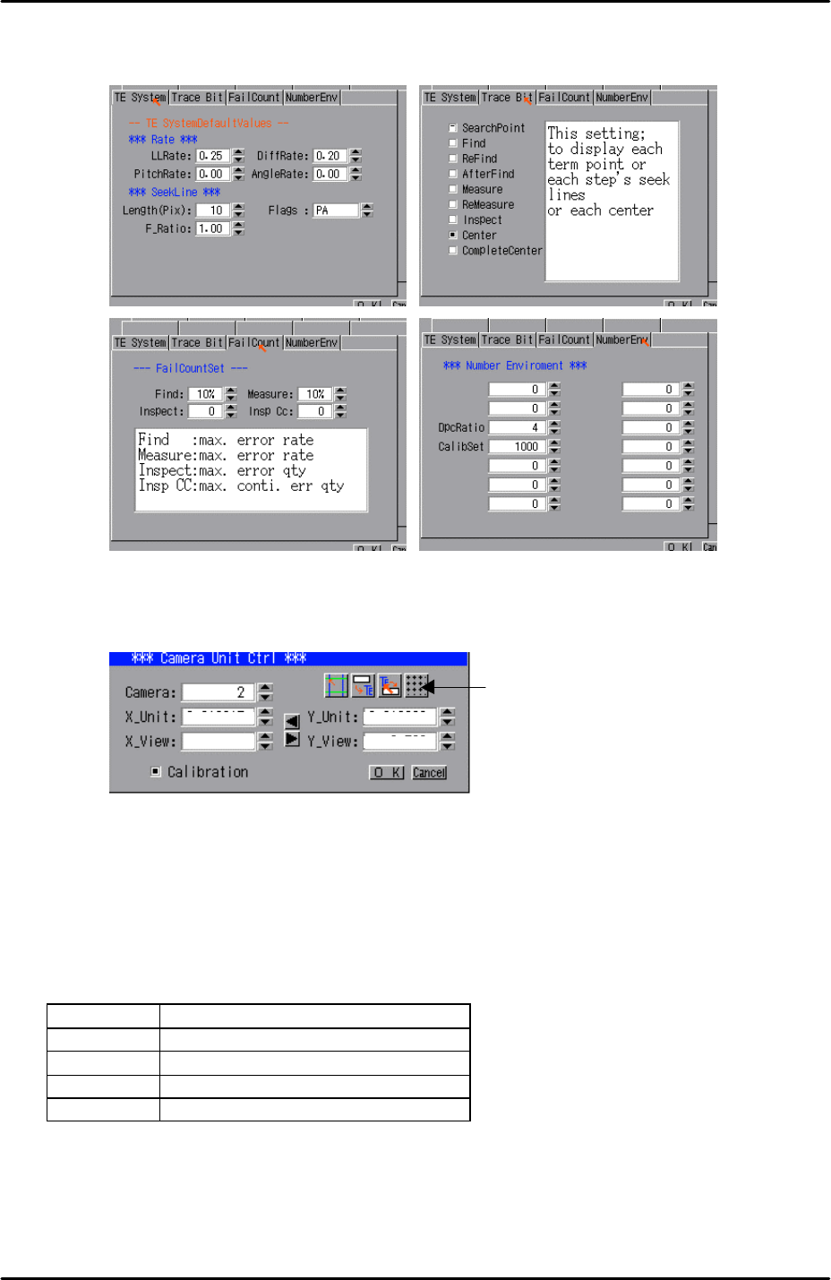
9. Select [Utility] – [Default Setting] and confirm that the default settings are identical to
those shown below, note that the default settings are the same for the parts camera and
FK-9F98-29 XP Series Training Text for Service Engineers
Edition 5.0 XP141 – Chapter 6 Proper Data Measurements Page 10 of 26
Fuji Machine Mfg. Co., Ltd. Okazaki
SMT Equipment Quality Assurance Dept.
6 – 10 CS Section
the mark camera:
10. Select [Utility] – [Scale Setting] – [Camera 2] – and click on the resolution measurement
tab:
11. Answer YES to the question “set center?” and the resolution measurement will proceed.
12. Answer NO to the question “Do you save calibration data to FD?”
13. To the next question “Save calibration data?” answer YES.
14. Confirm that the resolution results are within the tolerances described below:
Mark camera tolerance
X_Unit 0.0140 ~ 0.0147
X_View 8.9 ~ 9.5
Y_Unit 0.0140~ 0.0147
Y_View 6.56 ~ 6.95
15. The resolution measurement is now complete, right click on the screen and select
[Return].
16. Remember to remove the black cardboard roll from the mark camera light source.
Resolution
Measurement