xp141-241-341-5.0E.pdf - 第65页
FK-9F98- 29 XP Series Training Text for Service Engineers Edition 5.0 XP141 – Chapter 6 Proper Data Measurements Page 10 of 26 Fuji Machine Mfg. Co., Ltd. Okazaki SMT Equipment Quality Assurance Dept. 6 – 10 CS Section t…
FK-9F98-29 XP Series Training Text for Service Engineers
Edition 5.0 XP141 – Chapter 6 Proper Data Measurements Page 9 of 26
Fuji Machine Mfg. Co., Ltd. Okazaki
SMT Equipment Quality Assurance Dept.
6 – 9 CS Section
Mark camera brightness measurement
1. Clamp the plate jig in the main conveyor.
2. Place the color sample disc on top of the plate jig.
3. Select [Maintenance A] – [Jog] – [Fiducial] – the light comes ON for the mark camera and
the live image is displayed on the screen.
4. Inch the mark camera above the color sample disc and touch the image on the screen. A
brightness value will appear.
5. Set the brightness value to 130 +/- 10 by turning the gain adjusting screw on top of the
mark camera.
6. The brightness value will vary slightly at different points on the color sample image,
therefore set the average value to 130.
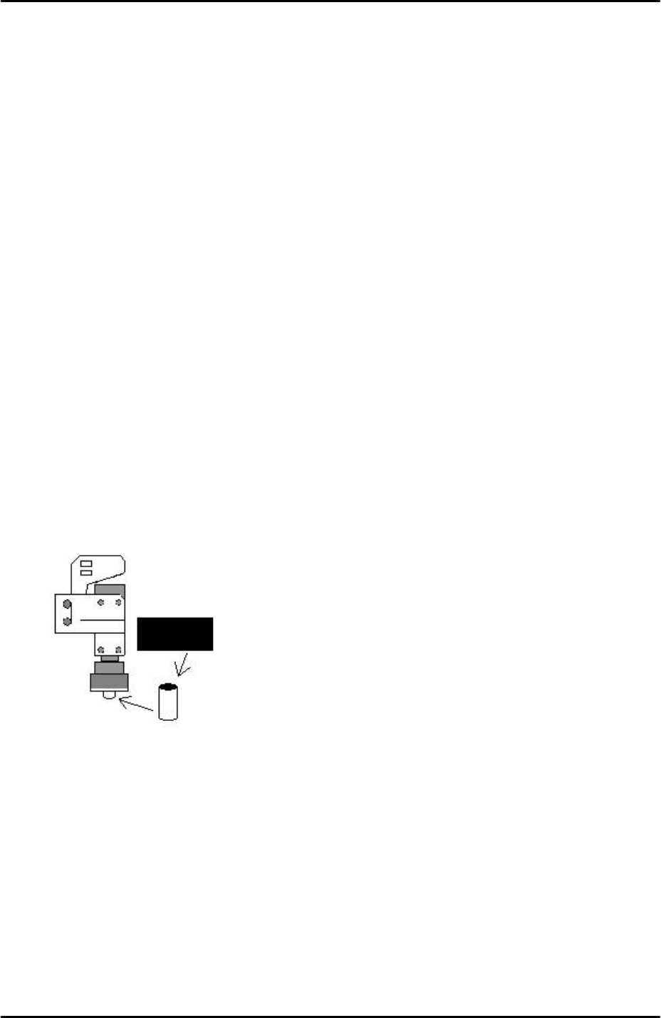
6.7 Measuring the mark camera resolution
1. Equipment: mark camera resolution measurement jig (Z3502DEAJ0020).
2. Clamp the resolution jig in the main conveyor. It should be flush with the reference rail,
and the printed surface should be uppermost.
3. Insert a rolled up piece of black cardboard inside the mark camera light source. This acts
as a shade to reduce the light intensity during the resolution measurement:
4. Select [Maintenance A] – [Jog] – [Fiducial] – the fiducial lamp comes ON and the mark
camera live image is displayed on the screen.
5. Inch the mark camera over the center of the resolution jig.
6. Select the cross hairs and set the center of the cross hairs in the center of the resolution
jig center dot.
7. Select [Maintenance A] – [I/O Check] – [Y010 fiducial lamp] – ON.
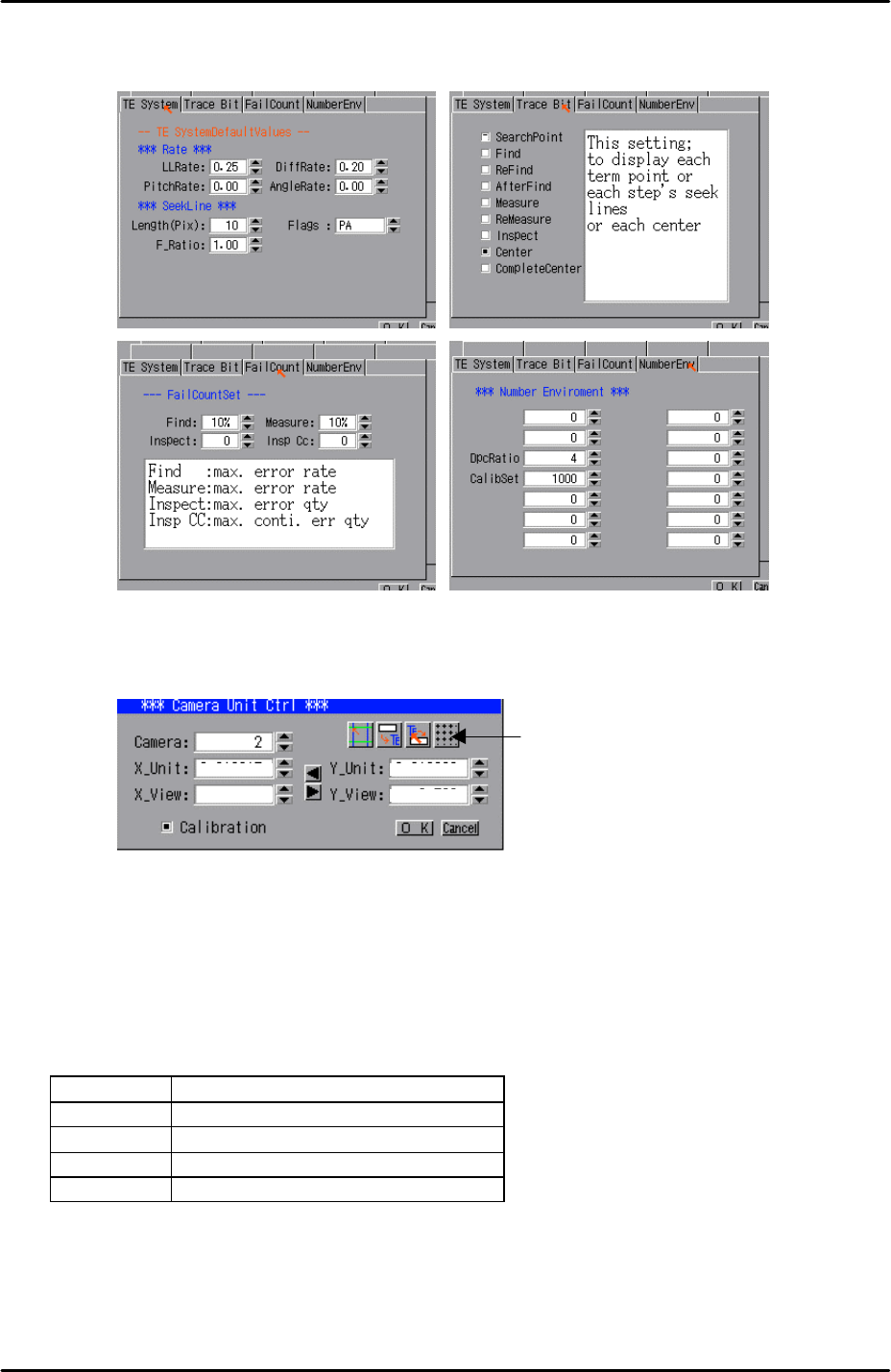
8. Select [Program] – [Template Editor] and right click on the screen to display a menu box.
9. Select [Utility] – [Default Setting] and confirm that the default settings are identical to
those shown below, note that the default settings are the same for the parts camera and
FK-9F98-29 XP Series Training Text for Service Engineers
Edition 5.0 XP141 – Chapter 6 Proper Data Measurements Page 10 of 26
Fuji Machine Mfg. Co., Ltd. Okazaki
SMT Equipment Quality Assurance Dept.
6 – 10 CS Section
the mark camera:
10. Select [Utility] – [Scale Setting] – [Camera 2] – and click on the resolution measurement
tab:
11. Answer YES to the question “set center?” and the resolution measurement will proceed.
12. Answer NO to the question “Do you save calibration data to FD?”
13. To the next question “Save calibration data?” answer YES.
14. Confirm that the resolution results are within the tolerances described below:
Mark camera tolerance
X_Unit 0.0140 ~ 0.0147
X_View 8.9 ~ 9.5
Y_Unit 0.0140~ 0.0147
Y_View 6.56 ~ 6.95
15. The resolution measurement is now complete, right click on the screen and select
[Return].
16. Remember to remove the black cardboard roll from the mark camera light source.
Resolution
Measurement
FK-9F98-29 XP Series Training Text for Service Engineers
Edition 5.0 XP141 – Chapter 6 Proper Data Measurements Page 11 of 26
Fuji Machine Mfg. Co., Ltd. Okazaki
SMT Equipment Quality Assurance Dept.
6 – 11 CS Section
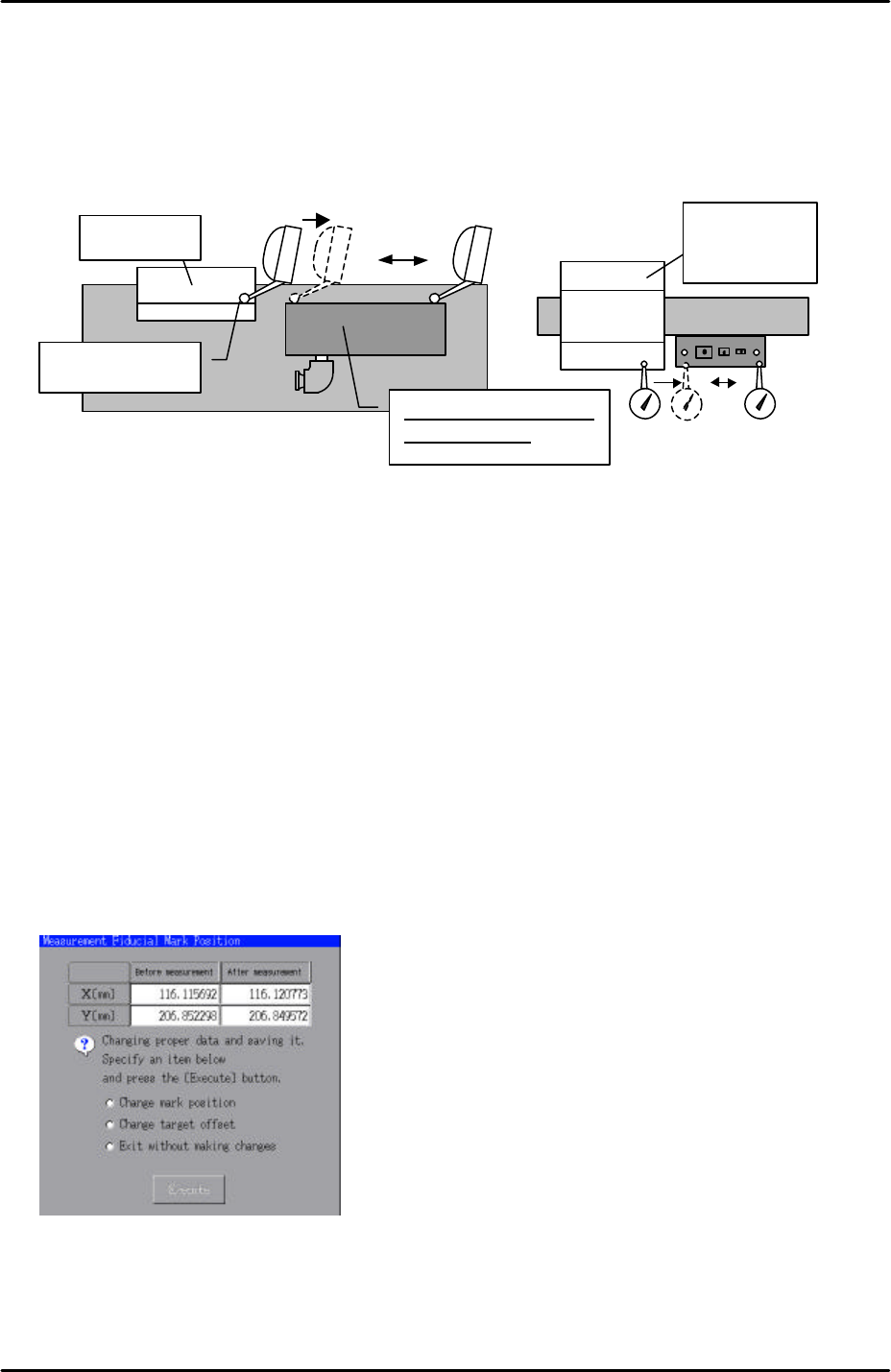
6.8 Measuring the mark camera orientation
1. Equipment: lever type dial gage (0.01mm). Parts gage station height adjustment jig
(A9531DEPJ1250).
2. Refer to the diagram below and put the height adjustment jig on the reference rail
adjacent to the parts gage station:
3. Use an extension bar to attach the dial gage to the placing head and set the dial gage on
the height adjustment jig as shown in the above diagram.
4. Set the dial gage to 0 on the reference side of the height adjustment jig and adjust the
height and flatness of the parts gage station. The height of the parts gage station should
be set to the same height as the height adjustment jig; tolerance is +/- 0.05mm. The
difference in flatness between the lowest and highest parts of the parts gage station
should be within 0.05mm.
5. Select [Maintenance A] – [Jog] – [Fiducial] – the fiducial lamp comes ON and the mark
camera live image is displayed on the screen.
6. Select the cross hairs and then center the mark camera in the center of the parts gage
station left hand fiducial mark.
7. Select [Maintenance C] – [Mark Camera Measurement] – [F MarkPos Measure] –
[START] to measure the position of the fiducial mark. The following dialogue box will
then display:
8. Select [Change mark position] – [Execute] to save the results of the measurement.
9. With the mark camera still centered on the fiducial mark select [Angle Measure] –
[START] to measure the mark camera Q (theta) orientation. To save the calibration
results press [OK].
Height jig
Height jig
Z9531DEPJ1250
Set the dial to “0”
Flatness should be
within 0.05mm