xp141-241-341-5.0E.pdf - 第70页
FK-9F98- 29 XP Series Training Text for Service Engineers Edition 5.0 XP141 – Chapter 6 Proper Data Measurements Page 15 of 26 Fuji Machine Mfg. Co., Ltd. Okazaki SMT Equipment Quality Assurance Dept. 6 – 15 CS Section 6…

FK-9F98-29 XP Series Training Text for Service Engineers
Edition 5.0 XP141 – Chapter 6 Proper Data Measurements Page 14 of 26
Fuji Machine Mfg. Co., Ltd. Okazaki
SMT Equipment Quality Assurance Dept.
6 – 14 CS Section
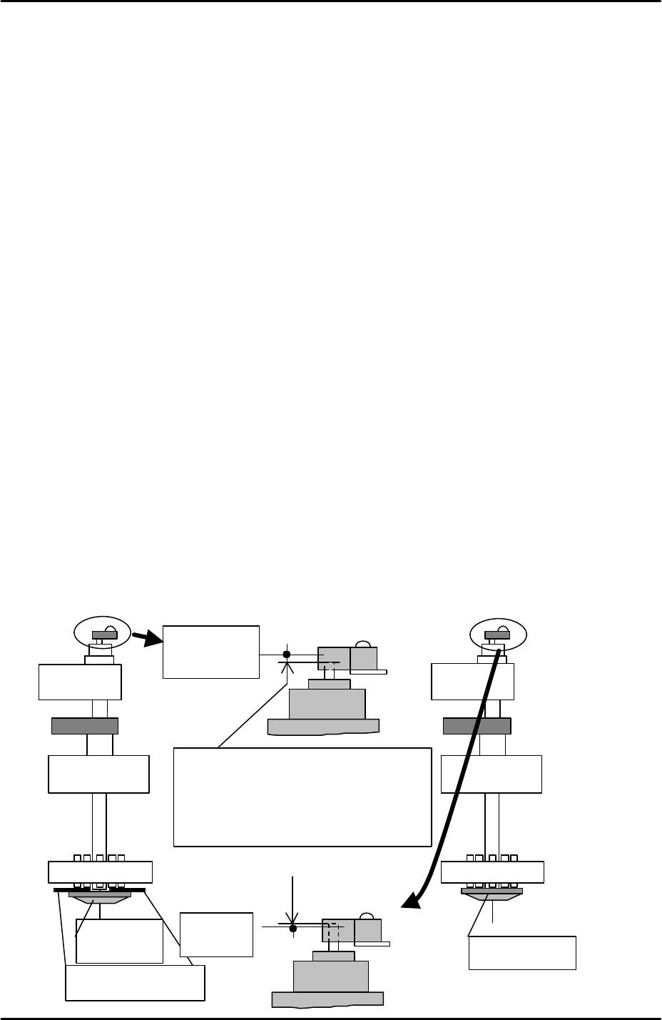
6. Lower the Z-axis and use the dial indicator to find the point where the pusher and piston
first contact.
7. Raise the Z-axis 0.1mm from this point and select [Maintenance C] – [Proper Data Editor]
– [Nozzle Position] – [Z_NzlPosZH] – [Direct Servo Input] to save the current Z-axis
counter value to proper data.
8. Rotate the Q axis pusher to confirm that at this height there is no interference between
the nozzle pistons and the pusher.
9. Once this proper data item has been input it is safe to use the “Retract Head” command
in the [Production] screen.
0.1mm
FK-9F98-29 XP Series Training Text for Service Engineers
Edition 5.0 XP141 – Chapter 6 Proper Data Measurements Page 15 of 26
Fuji Machine Mfg. Co., Ltd. Okazaki
SMT Equipment Quality Assurance Dept.
6 – 15 CS Section
6.12 Reset cylinder
1. Select [Maintenance A] – [I/O Check] – [Y01F ResetCylinder] – ON to raise the reset
cylinder.
2. Confirm that the clearance between the reset cylinder and the vacuum/air blow pins is
within the range 0 to 0.50mm. This clearance is non-adjustable, so if outside of the
range, please contact Fuji.
Reset cylinder sensor adjustment
1. Select [Maintenance A] – [I/O Check] – [Y01F ResetCylinder] – OFF to lower the reset
cylinder.
2. Place a 1.0mm feeler gage between the reset cylinder and the vacuum/air blow pins.
3. Select [Maintenance A] – [I/O Check] – [Y01F ResetCylinder] – ON to raise the reset
cylinder making sure that the 1.0mm feeler gage remains between the reset cylinder and
the Vacuum/air blow pins. Take care not to trap your fingers when carrying this out.
4. Select [Maintenance A] – [I/O Check] – [X012 ResetCylUpChk] so that the sensor status
can be monitored. Note that the sensor is “Dark ON”, therefore the sensor output is ON
when the sensor light is OFF.
5. Loosen the reset cylinder sensor bracket bolts and lower the sensor until it comes ON,
then raise it until it just comes OFF. Lock the sensor bracket at this position.
6. Lower and then raise the reset cylinder and confirm that with the 1.0mm feeler gage in
place the reset cylinder sensor does not come ON.
7. Remove the 1.0mm feeler gage and raise the reset cylinder, confirm that the reset
cylinder sensor is ON at this position.
Reset
Cylinder
1.0mm feeler gauge
Sensor
turns
On
Sensor turns
OFF
Insert the 1.0mm feeler gauge. When the
reset cylinder is up, the upper limit check
sensor should turn Off. And sensor
should turn On when the 1.0mm feeler
gauge is removed.
Reset Cylinder
FK-9F98-29 XP Series Training Text for Service Engineers
Edition 5.0 XP141 – Chapter 6 Proper Data Measurements Page 16 of 26
Fuji Machine Mfg. Co., Ltd. Okazaki
SMT Equipment Quality Assurance Dept.
6 – 16 CS Section
8. Ensure that the reset cylinder sensor is positioned so that the reset cylinder rod is in the
center of the sensor.
6.13 Measuring the R-axis offset
1. Insert 1.3mm nozzles in all 12 nozzle slots.
2. Select [Production] – [Nozzle Editor] – and set the nozzle configuration in the editor to
match the actual configuration of nozzles on the revolver.
3. Inch the Y-axis to the “PrismFront” position (see 6.2 “camera centering” steps 12 and 13).
4. Select [Maintenance A] – [Jog] – [Side1] to activate the side 1 prism light source and
display the parts camera live image.
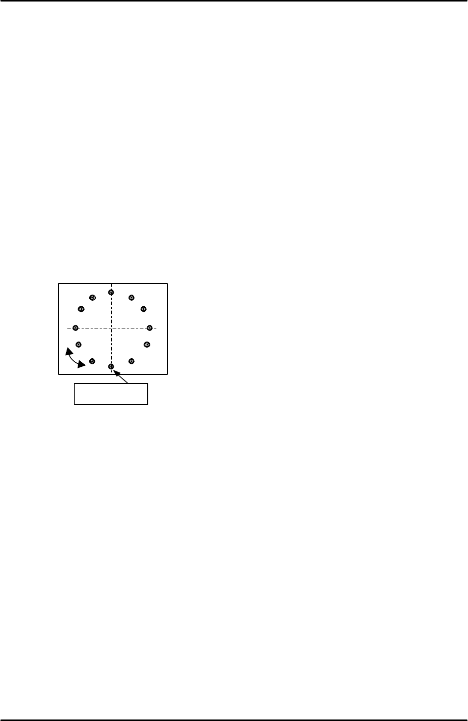
5. Bring nozzle no.1 to the front of the machine and display the cross hairs.
6. Rotate the R axis until the vertical cross hair is aligned with nozzles 1 and 7, and the
horizontal cross hair is aligned with nozzles 4 and 10.
7. Select [Maintenance C] – [R axis offset] – [Start] – [START] to measure the R axis offset.
After the calibration is complete press [OK] to save the results.
8. Select [Maintenance C] – [Proper Data Editor] – [Servo Ofst] – [Target Ofst_R] and
confirm that the results of the measurement have been saved in proper data.
9. If the R-axis offset could not be measured because the counter was out of range carry
out the following procedure:
10. Inch the Y-axis to the “PrismFront” position (see 6.2 “camera centering” steps 12 and 13).
11. Select [Maintenance A] – [Jog] – [Side1] to activate the side 1 prism light source and
display the parts camera live image.
12. Bring nozzle no.1 to the front of the machine and display the cross hairs.
13. Rotate the R-axis until the vertical cross hair is aligned with nozzles 1 and 7, and the
horizontal cross hair is aligned with nozzles 4 and 10 (see the diagram above).
14. Select [Maintenance C] – [Stroke Ofst] – and press the red key in between the two blue
inching arrows of the R axis.
15. Repeat steps 3 to 8.
Nozzle No. 1
No.7
No.4No.10