xp141-241-341-5.0E.pdf - 第73页
FK-9F98- 29 XP Series Training Text for Service Engineers Edition 5.0 XP141 – Chapter 6 Proper Data Measurements Page 18 of 26 Fuji Machine Mfg. Co., Ltd. Okazaki SMT Equipment Quality Assurance Dept. 6 – 18 CS Section 6…
FK-9F98-29 XP Series Training Text for Service Engineers
Edition 5.0 XP141 – Chapter 6 Proper Data Measurements Page 17 of 26
Fuji Machine Mfg. Co., Ltd. Okazaki
SMT Equipment Quality Assurance Dept.
6 – 17 CS Section
6.14 Measuring the Q-axis offset
1. Bring the R-axis counter value to 0 and press the emergency stop button.
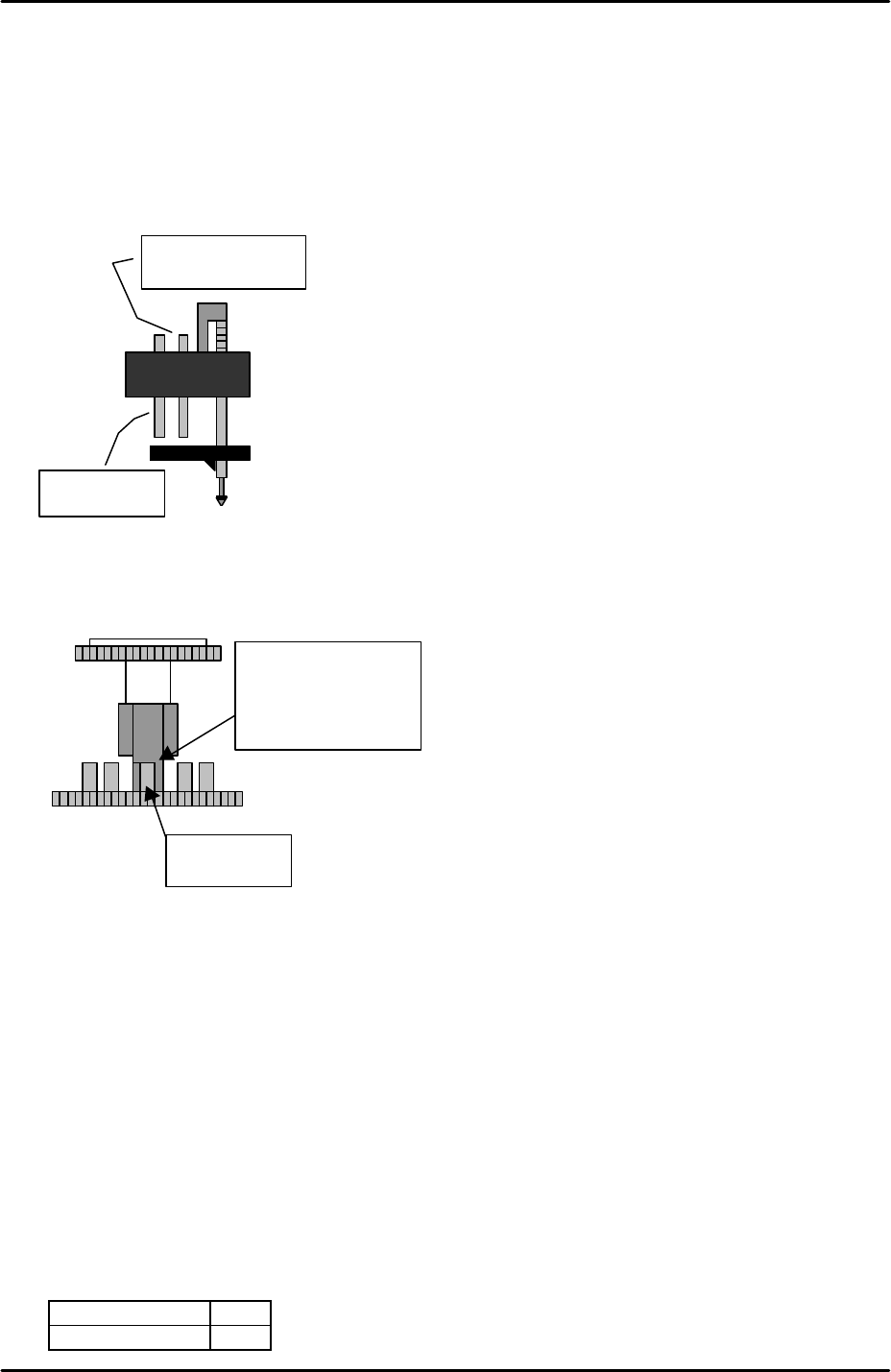
2. Bring the Q-axis pusher above the nozzle no.1 piston.
3. Descend the pusher so that it comes down to the right of the air blow pin and reaches its
lower limit.
4. Rotate the Q axis clockwise until the pusher contacts the air blow pin. At this point the Q
axis and R axis can rotate in tandem. Rotate the Q axis until the R-axis counter value
exceeds 0.
5. With the Q and R axis still in tandem rotate the R axis slowly anti-clockwise until the R-
axis counter value returns to 0.
6. Record the Q axis counter value at this point and subtract 5.5 degrees from this value to
get a new value.
7. Raise the Q axis pusher to a height where it no longer interferes with the R-axis.
8. Bring the Q axis counter to the new value and then select [Maintenance C] – [Stroke
Offset] – then press the red key in between the two blue inching arrows of the Q axis.
Here the current counter value is entered automatically in [Maintenance C] – [Proper
Data Editor] – [Servo Ofst] – [TargetOfst_Q].
9. Select [Maintenance C] – [Proper Data Editor] – [Machine Origin] –
[Q_PosPick1/Q_PosPlace1] and enter the following values:
Q_PosPick1 6.5
Q_PosPlace1 0
Air blow pin
Parts vacuum pin
Place the Q-axis
pusher against the
right side surface of
the air blow pin.
Air blow pin
FK-9F98-29 XP Series Training Text for Service Engineers
Edition 5.0 XP141 – Chapter 6 Proper Data Measurements Page 18 of 26
Fuji Machine Mfg. Co., Ltd. Okazaki
SMT Equipment Quality Assurance Dept.
6 – 18 CS Section
6.15 Measuring the MFU pickup position
1. Equipment: pickup position measurement jig.
2. Attach the MFUs to side1 and side2.
3. Mount the pick up position measurement jig at D25 on side1.
4. Bring the R axis counter to 0 so that the nozzle no.1 piston comes to the front of the
machine.
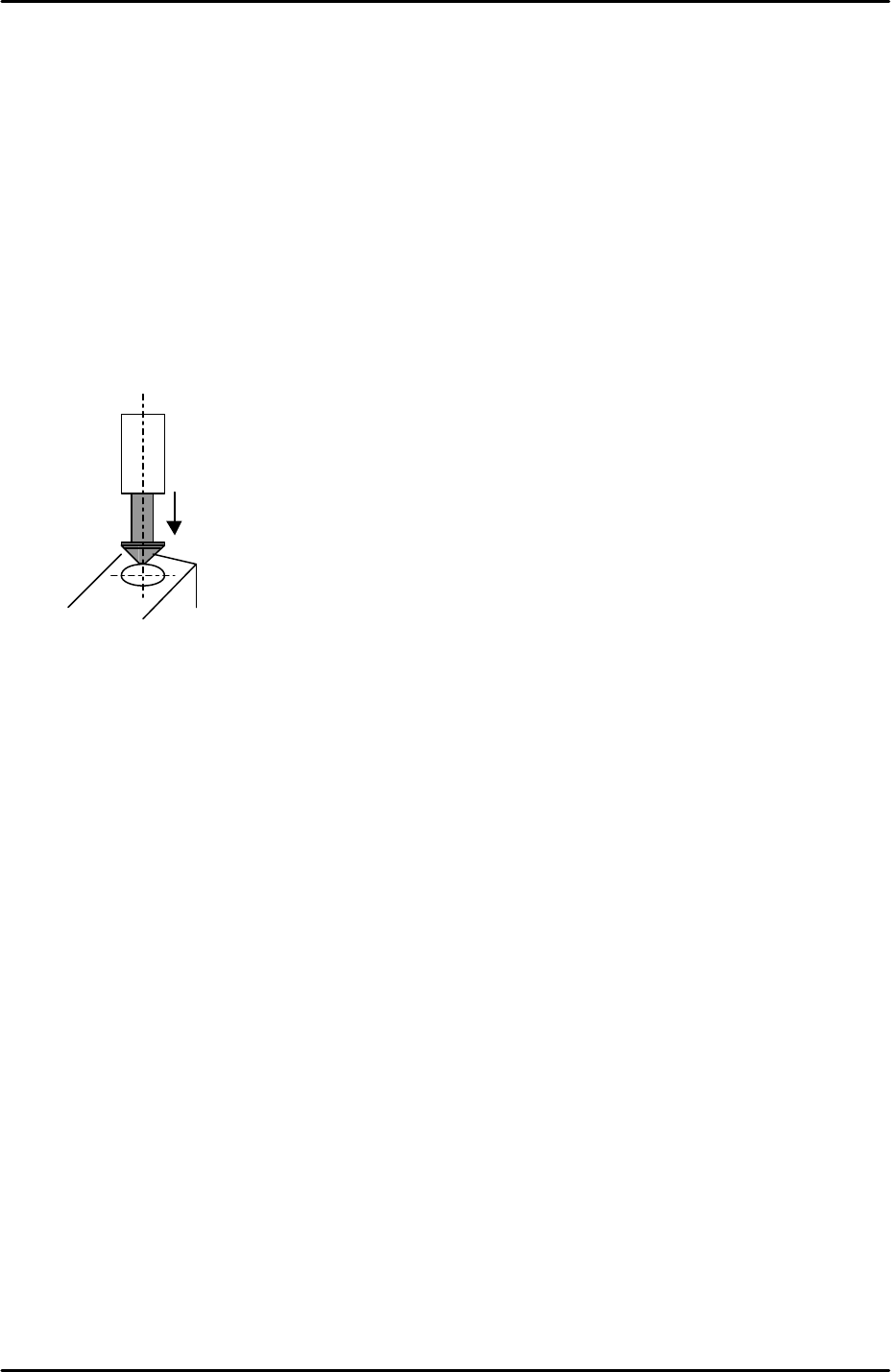
5. Insert a 0.4mm nozzle in the nozzle no.1 piston.
6. Align the 0.4mm nozzle directly above the circular mark on the pick up position
measurement jig.
7. Select [Maintenance C] – [Proper Data Editor] – [X_stage1org] and [Y_stage1org] –
[Direct Servo Input] to save the current X and Y-axis counter values to proper data.
8. Bring the R axis counter value to 180 degrees and repeat the procedure for the side 2
MFU pick up position [X_stage2org] and [Y_stage2org].
6.16 Pickup height measurement
1. Equipment: pick up height measurement jig with dial gage (0.005mm). (Z9064AVJ5540).
Nozzle Jig (A5706ASEAJ8100).
2. Place the pick up height measurement jig in slot 25 of the side1 MFU.
3. Remove all nozzles and insert the nozzle jig in nozzle slot no.1.
4. Bring the R axis to 0 and align the Q axis pusher above the nozzle no.1 piston.
5. Bring the nozzle jig above the pick up height measurement jig dial gage and descend the
Z axis until the dial gage indicates a pick up height of 0.650mm (here the dial gage will be
0). Record the Z-axis counter value at this point.
6. Repeat the measurement for all 12 of the nozzle pistons. The following table lists the R-
axis angle for each nozzle pick up height measurement:
FK-9F98-29 XP Series Training Text for Service Engineers
Edition 5.0 XP141 – Chapter 6 Proper Data Measurements Page 19 of 26
Fuji Machine Mfg. Co., Ltd. Okazaki
SMT Equipment Quality Assurance Dept.
6 – 19 CS Section
Nozzle No. R axis angle Z count
1 0
2 30
3 60
4 90
5 120
6 150
7 180
8 210
9 240
10 270
11 300
12 330
7. Record the Z-axis counter value for all 12 nozzle pistons and calculate the average.
From the average value subtract 0.25mm (-0.25mm) and input this value at [Maintenance
C] – [Proper Data Editor] – [Machine Origin] – [Z_Stage1 Surface].
8. Repeat the procedure for side2 [Z_Stage2 Surface].
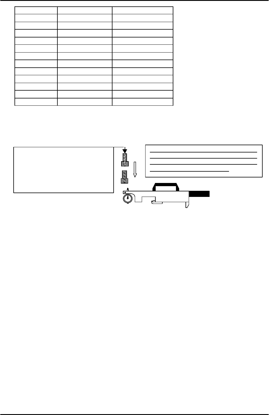
Set
the
dial to
“
0
”
at the master jig,
attach
the
nozzle jig (A5706ADEAJ8100) to the piston
and lower the Z-axis. Pick up height is the
position where the dial shows “0”.
<NOTE>
There is a tap hole at the nozzle jig
(A5706ADEAJ8100). Be careful the tip
of the dial does not go in the tap hole
as this will effect the measurement
results.