xp141-241-341-5.0E.pdf - 第84页
FK-9F98- 29 XP Series Training Text for Service Engineers Edition 5.0 XP141 – Chapter 7 Operation and Accuracy Page 2 of 4 Fuji Machine Mfg. Co., Ltd. Okazaki SMT Equipment Quality Assurance Dept. 7 – 2 CS Section 5. Set…
FK-9F98-29 XP Series Training Text for Service Engineers
Edition 5.0 XP141 – Chapter 7 Operation and Accuracy Page 1 of 4
Fuji Machine Mfg. Co., Ltd. Okazaki
SMT Equipment Quality Assurance Dept.
7 – 1 CS Section
Chapter 7 – Checking operation and accuracy
7.1 Checking idle operation
1. Transmit the idle program “XP1_IDLE” to the machine.
2. Ensure that there are no feeders in the MFU and no nozzles in the revolver.
3. Select [Production] – [Nozzle Editor] – and set all 12 nozzle diameter entries to 1.3mm.
4. Set the conveyor at its maximum width of 356mm.
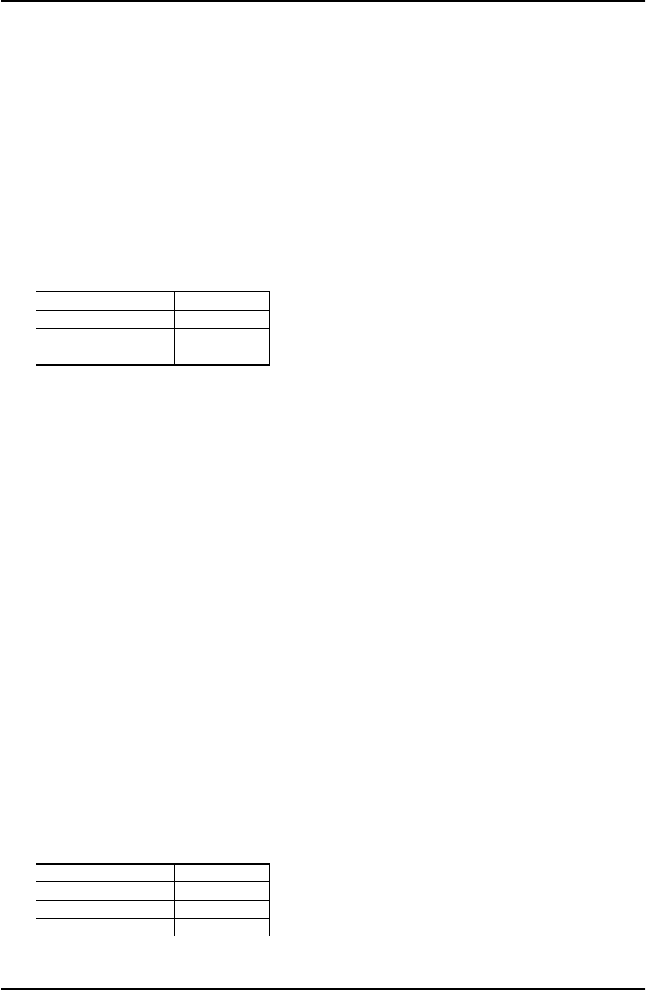
5. Select [Maintenance A] – [Select Mode] and set the mode as detailed in the following
table:
Operation Mode Idle
Production Mode Automatic
Error handling Error Stop
Acceleration rate 0.1
6. Check for any mechanical interference in the machine then select [Production] –
[Automatic] – [START] to commence idling.
7. Check that there are no irregular noises or movements in the machine and then gradually
increase the acceleration rate up to a maximum 0f 1.0.
8. The machine should be run for at least 12 hours without stopping, and in total for at least
30 hours.
9. After idling is complete check the machine for any irregularities.
7.2 Placing Accuracy Measurement
1. Equipment: glass board (Z5314CGPJ0120) with white background and double-sided
sticky tape. 12 x 1.3mm white nozzles. 3216 black PAM parts.
2. Transmit the relevant program to the machine. Side1: [G_3216PAM-18]. Side2:
[G_3216PAME-18].
3. Select [Production] – [Select Program] – [G_3216PAM-18] – [Download] to bring the
program into the machine foreground.
4. Select [Maintenance A] – [Select Mode] – and set the mode as detailed in the following
table:
Operation Mode Production
Production Mode Automatic
Error handling Error Pass
Acceleration Rate 1.0

FK-9F98-29 XP Series Training Text for Service Engineers
Edition 5.0 XP141 – Chapter 7 Operation and Accuracy Page 2 of 4
Fuji Machine Mfg. Co., Ltd. Okazaki
SMT Equipment Quality Assurance Dept.
7 – 2 CS Section
5. Set 1.3mm black nozzles in all 12 nozzle slots on the revolver.
6. Select [Production] – [Nozzle Editor] – and set all 12 nozzle diameter entries to 1.3mm
then carry out a [Size Check].
7. Ensure that the central parts gage ceramic chip (3mm X 1.6mm) is in place in the parts
gage station as this is required for nozzle center measurement. Also ensure that the left
and right hand parts gage ceramic chips are in their indentations on the parts gage
station; otherwise air leaking from the vacant vacuum holes may blow away the central
ceramic chip.
8. If PAM is being carried out for the first time select [Production] – [Nozzle Center
Measurement] – [Side1] – Acceleration rate [1.0] – [Rotate Center Measurement] and the
rotate center measurement proceeds. Prior to PAM this measurement should be carried
out at least 5 times.
9. Select [Production] – [Nozzle Center Measurement] – [Nozzle Center Measurement] and
the nozzle center measurement proceeds.
10. Remove all of the black 1.3mm nozzles and replace them with white 1.3mm nozzles.
11. Select [Production] – [Feeder Data] – and check which device slot the parts will be picked
up from. Place a feeder equipped with PAM parts in this slot.
12. Place the glass board in the IN conveyor, then select [Production] – [Automatic] – [Start]
the board loads and placement proceeds.
13. When the placing sequences are finished press the CYCLE STOP button.
14. Leave the board in the conveyor and select [Maintenance C] – [Accuracy Measurement]
– [Select Program] – [G_3216PAM-18] – [Start] to measure the placement accuracy.
15. When the measurement is complete, the results window will open, and a placing offset
can be made by pressing the [Front Offset] tab.
16. Repeat the process until the placement accuracy results are within the tolerances
described in the following table:
Average Maximum Minimum 3 Sigma
X and Y (mm)
+/- 0.020 0.060 -0.060 +/-0.066
Theta (degrees)
+/- 0.050 Not Specified Not Specified Not Specified
17. Repeat for side2.
Explanation of “Camera Distance” proper data
1. The camera distance proper data is the distance from the revolver center to the mark
camera center. It is measured during [Rotate Center Measurement]. Whenever
components are placed at angles other than 0 degrees, the revolver center (Rotate
Center) is referenced together with the nozzle center.
2. If the camera distance proper data is incorrect it may be impossible to pick up the parts
gage ceramic chips during [Rotate Center Measurement]. In this case manually offset
the Camera Distance proper data until the nozzle picks up the parts gage ceramic chip in
the center of the parts gage cavity. At this stage it may be useful to reduce the

FK-9F98-29 XP Series Training Text for Service Engineers
Edition 5.0 XP141 – Chapter 7 Operation and Accuracy Page 3 of 4
Fuji Machine Mfg. Co., Ltd. Okazaki
SMT Equipment Quality Assurance Dept.
7 – 3 CS Section
acceleration rate to improve the chances of picking up the parts gage ceramic chips.
Once the parts gage is picked up check that it is replaced in the parts gage cavity and is
not overhanging the lip of the cavity.
3. Now [Rotate Center Measurement] can be performed and the camera distance that you
have input manually will be overwritten with more accurate data taken from the vision
processing.
4. Camera Distance proper data can be found in [Maintenance C] – [Proper Data Editor] –
[Camera Offset] – [Camera1DistanceX] and [Camera1DistanceY]. Check the proper data
list for the default values.