xp141-241-341-5.0E.pdf - 第91页
C C h h a a p p t t e e r r 1 1 I I n n i i t t i i a a l l A A d d j j u u s s t t m m e e n n t t

FK-9F98-29 XP Series Training Text for Service Engineers
Edition 5.0 XP241E Contents
Fuji Machine Mfg. Co., Ltd. Okazaki.
SMT Equipment Quality Assurance Dept.
CS Section
9.10 T-tray origin (magazine adjustment and measurement)............................ 9-6
9.11 Guide rail adjustment.................................................................................. 9-7
9.12 U-axis clamper parallelism check and adjustment.................................... 9-7
9.13 Shuttle rail position adjustment.................................................................. 9-7
9.14 Tray pusher adjustment 1........................................................................... 9-8
9.15 Tray pusher adjustment 2........................................................................... 9-9
9.16 Shuttle clamping position adjustment........................................................ 9-11
9.17 U-axis interlock sensor adjustment............................................................ 9-12
9.18 Tray height check sensor and [T_TrayEmptyOrg] measurement............. 9-13
9.19 Tray shutter check sensor adjustment ...................................................... 9-13
9.20 Tray pallet interference check sensor amplifier adjustment...................... 9-14
9.21 Tray pitch offset measurement................................................................... 9-15
9.22 Tray pickup position check sensor adjustment.......................................... 9-16
9.23 Tray catch stopper adjustment................................................................... 9-17
9.24 Shuttle clamp position check...................................................................... 9-18
9.25 Tray detection sensor adjustment.............................................................. 9-19
9.26 Tray pickup position measurement............................................................ 9-19
9.27 Returning proper data................................................................................. 9-20
9.28 Re-tightening check.................................................................................... 9-20
9-29 Final Check................................................................................................. 9-21
9-30 Backing Up.................................................................................................. 9-21
Supplemental Information
XP241E Servo Amp Parameter List
V1.40 Proper Data List
Jig Catalogue
Mechanical Stopper Locations
Servo Amp Battery Replacement Procedure
VME Rack Configuration
Pressure Sensor User Manual

C
C
h
h
a
a
p
p
t
t
e
e
r
r
1
1
I
I
n
n
i
i
t
t
i
i
a
a
l
l
A
A
d
d
j
j
u
u
s
s
t
t
m
m
e
e
n
n
t
t
FK-9F98-29 XP Series Training Text for Service Engineers
Edition 5.0 XP241 – Chapter 1 Initial Adjustment Page 1 of 8
Fuji Machine Mfg. Co., Ltd. Okazaki.
SMT Equipment Quality Assurance Dept.
1 – 1 CS Section
Chapter 1 – Initial adjustment
1.1 Machine leveling
• Measuring equipment: track level (0.02/1000mm)
Before executing leveling carry out the following procedure:
1. On new machines remove the red bracket that secures the X and Y axes during transit.
2. Remove the IN and OUT side conveyor covers.
3. Remove the mesh-cover that surrounds the MTU empty tray eject area at the rear of the
machine.
4. Check that the accessory parts are present. On a standard machine there should be:
4 back-up pins (Solid type)
1 Coupler for the air supply
1 Waste tape box
1 Lock
1 MFU
5. Remove the waste tape duct.
6. Check that the cooling fan is not blocked.
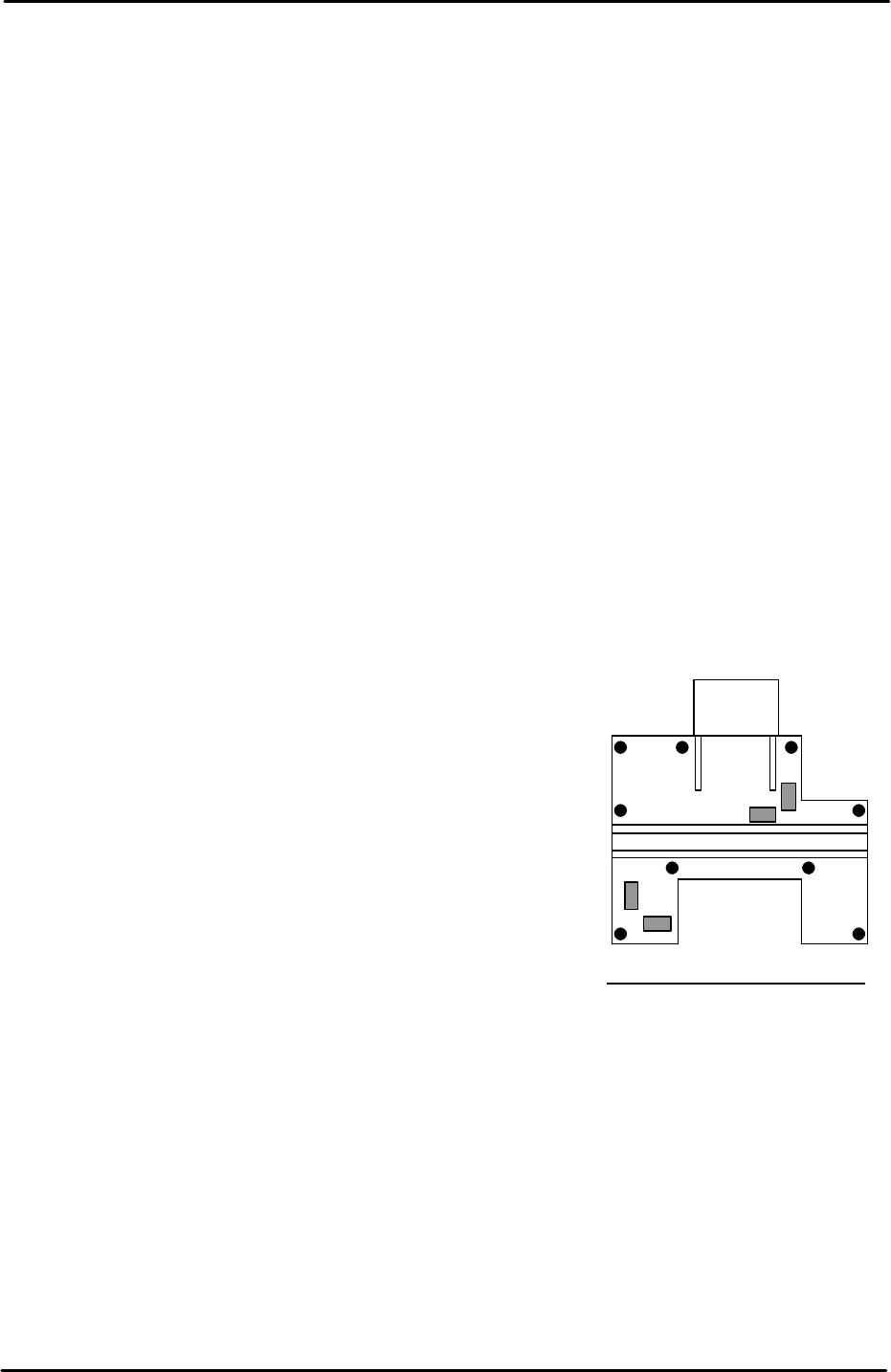
Machine leveling
1. Set two track levels on the machine at (position
A) and carry out initial leveling using leveling
bolts 1 to 4 as illustrated in the diagram.
2. After initial leveling is complete, set the track levels at
(position B) and confirm the machine is level. The track
levels should indicate that the machine is level at both
points A and B. If it proves impossible to level within
tolerance please contact FUJI.
3. After the initial leveling is confirmed, set leveling sheets
at the remaining points, and tighten the lock nuts for all
of the leveling bolts.
4. Finally confirm that all of the leveling sheets are stable,
and check once again that the leveling is within
tolerance.
A
B
1
4 3
2
Tolerance 0.10mm/1000mm