xp141-241-341-5.0E.pdf - 第92页
FK-9F98- 29 XP Series Training Text for Service Engineers Edition 5.0 XP241 – Chapter 1 Initial Adjustment Page 1 of 8 Fuji Machine Mfg. Co., Ltd. Okazaki. SMT Equipment Quality Assurance Dept . 1 – 1 CS Section Chapter …

C
C
h
h
a
a
p
p
t
t
e
e
r
r
1
1
I
I
n
n
i
i
t
t
i
i
a
a
l
l
A
A
d
d
j
j
u
u
s
s
t
t
m
m
e
e
n
n
t
t
FK-9F98-29 XP Series Training Text for Service Engineers
Edition 5.0 XP241 – Chapter 1 Initial Adjustment Page 1 of 8
Fuji Machine Mfg. Co., Ltd. Okazaki.
SMT Equipment Quality Assurance Dept.
1 – 1 CS Section
Chapter 1 – Initial adjustment
1.1 Machine leveling
• Measuring equipment: track level (0.02/1000mm)
Before executing leveling carry out the following procedure:
1. On new machines remove the red bracket that secures the X and Y axes during transit.
2. Remove the IN and OUT side conveyor covers.
3. Remove the mesh-cover that surrounds the MTU empty tray eject area at the rear of the
machine.
4. Check that the accessory parts are present. On a standard machine there should be:
4 back-up pins (Solid type)
1 Coupler for the air supply
1 Waste tape box
1 Lock
1 MFU
5. Remove the waste tape duct.
6. Check that the cooling fan is not blocked.
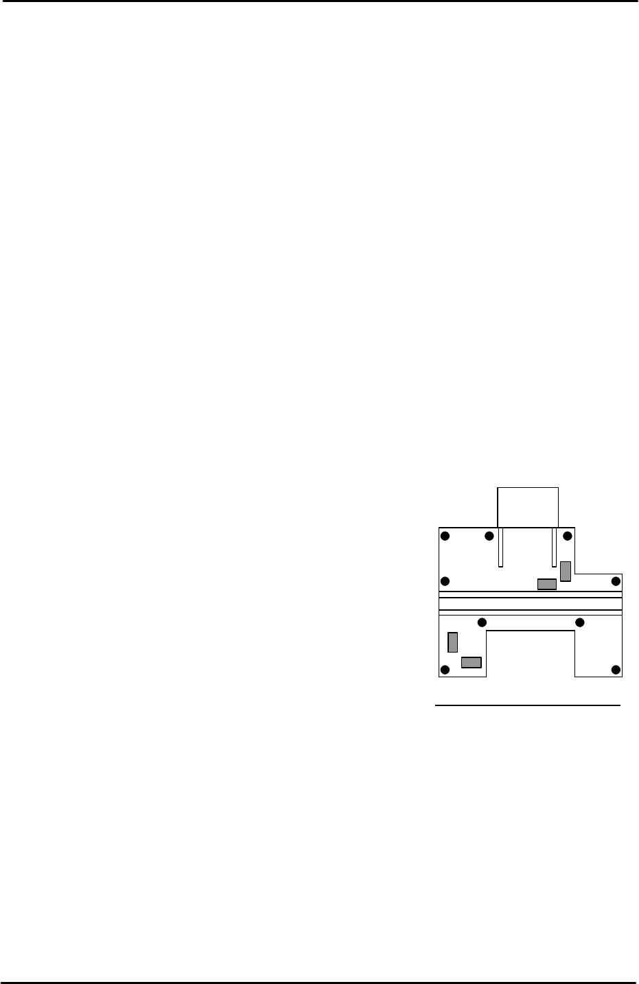
Machine leveling
1. Set two track levels on the machine at (position
A) and carry out initial leveling using leveling
bolts 1 to 4 as illustrated in the diagram.
2. After initial leveling is complete, set the track levels at
(position B) and confirm the machine is level. The track
levels should indicate that the machine is level at both
points A and B. If it proves impossible to level within
tolerance please contact FUJI.
3. After the initial leveling is confirmed, set leveling sheets
at the remaining points, and tighten the lock nuts for all
of the leveling bolts.
4. Finally confirm that all of the leveling sheets are stable,
and check once again that the leveling is within
tolerance.
A
B
1
4 3
2
Tolerance 0.10mm/1000mm
FK-9F98-29 XP Series Training Text for Service Engineers
Edition 5.0 XP241 – Chapter 1 Initial Adjustment Page 2 of 8
Fuji Machine Mfg. Co., Ltd. Okazaki.
SMT Equipment Quality Assurance Dept.
1 – 2 CS Section
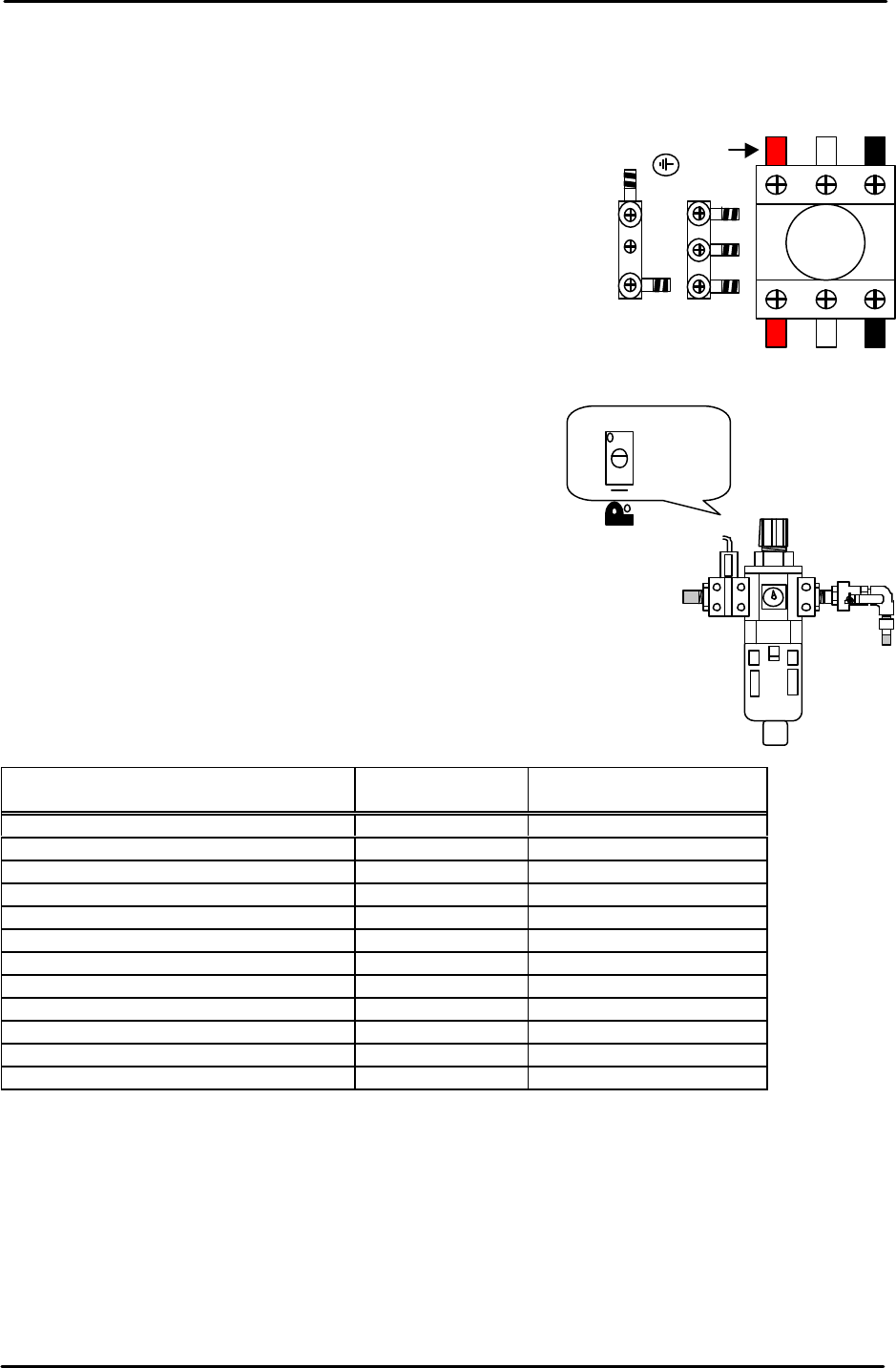
1.2 Power and air connection
Power supply connection
1. Open the power supply BOX at the lower right hand side of
the machine and pull the power line from the bottom of the
BOX.
2. Connect the ground terminal and the ground wire first.
3. Connect the three wires of the power supply cable to the
three breaker box (KG41B) terminals.
L1: red L2: white L3: black
Air hose connection
1. Connect the hose to the air inlet at the machine rear
side.
2. Check that the regulator setting is 0.5Mpa.
3. Turn ON the machine and adjust the pressure switch
screw so that the 200-volt power supply turns OFF
when the air pressure drops to 0.4Mpa and below.
1.3 Lubrication
Apply lubricant to the following areas:
Lubrication point
Daphne Eponex
No.2
Biral T&D
Z-axis ball screw O X
Spline shaft O X
Q-axis helical gear O X
Balls-crew (conveyor) O X
LM rail (conveyor) O X
Conveyor chain X O
Link arm sliding area (lifter plate) O X
Link arm sliding area (cutter) O X
LM rail (cutter) O X
LM rail (MTU) X O
Ball guide (MTU) O X
Ball-screw (MTU) O X
Note: Apply anticorrosion spray to the machine base, brackets, and other metal surfaces, to
prevent rust.
Note: Do not over apply lubricant to the ball screws, helical gears, LM guide rails, or other
parts of the machine that rotate or move at high velocity. Over lubrication may result in the
lubricant being flung around the machine and interfering with the sensors, vision processing,
and other aspects of the machine operation.
L1 L2 L3
Red
Adjustment screw