xp141-241-341-5.0E.pdf - 第94页
FK-9F98- 29 XP Series Training Text for Service Engineers Edition 5.0 XP241 – Chapter 1 Initial Adjustment Page 3 of 8 Fuji Machine Mfg. Co., Ltd. Okazaki. SMT Equipment Quality Assurance Dept . 1 – 3 CS Section 1.4 Belt…
FK-9F98-29 XP Series Training Text for Service Engineers
Edition 5.0 XP241 – Chapter 1 Initial Adjustment Page 2 of 8
Fuji Machine Mfg. Co., Ltd. Okazaki.
SMT Equipment Quality Assurance Dept.
1 – 2 CS Section
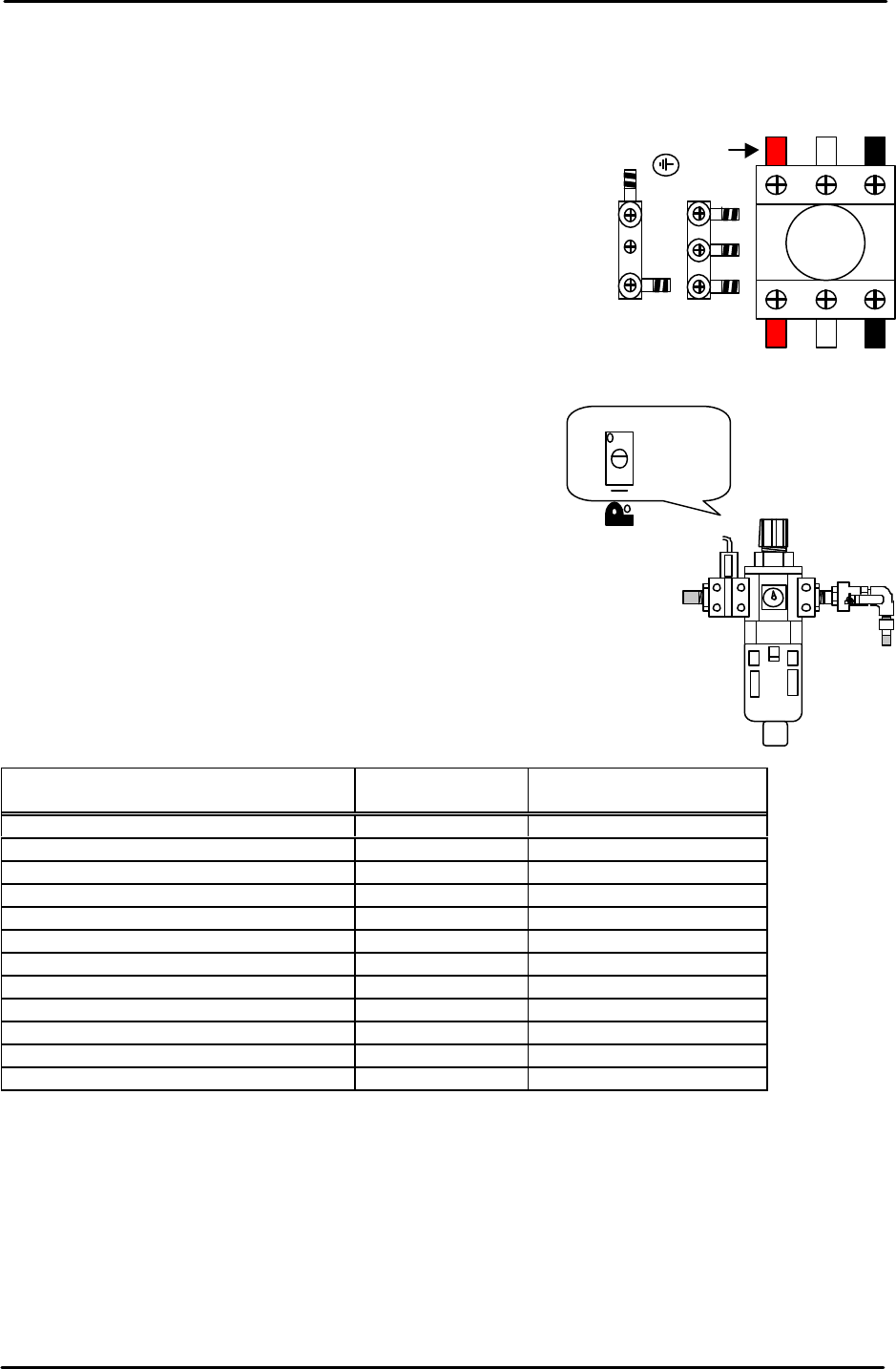
1.2 Power and air connection
Power supply connection
1. Open the power supply BOX at the lower right hand side of
the machine and pull the power line from the bottom of the
BOX.
2. Connect the ground terminal and the ground wire first.
3. Connect the three wires of the power supply cable to the
three breaker box (KG41B) terminals.
L1: red L2: white L3: black
Air hose connection
1. Connect the hose to the air inlet at the machine rear
side.
2. Check that the regulator setting is 0.5Mpa.
3. Turn ON the machine and adjust the pressure switch
screw so that the 200-volt power supply turns OFF
when the air pressure drops to 0.4Mpa and below.
1.3 Lubrication
Apply lubricant to the following areas:
Lubrication point
Daphne Eponex
No.2
Biral T&D
Z-axis ball screw O X
Spline shaft O X
Q-axis helical gear O X
Balls-crew (conveyor) O X
LM rail (conveyor) O X
Conveyor chain X O
Link arm sliding area (lifter plate) O X
Link arm sliding area (cutter) O X
LM rail (cutter) O X
LM rail (MTU) X O
Ball guide (MTU) O X
Ball-screw (MTU) O X
Note: Apply anticorrosion spray to the machine base, brackets, and other metal surfaces, to
prevent rust.
Note: Do not over apply lubricant to the ball screws, helical gears, LM guide rails, or other
parts of the machine that rotate or move at high velocity. Over lubrication may result in the
lubricant being flung around the machine and interfering with the sensors, vision processing,
and other aspects of the machine operation.
L1 L2 L3
Red
Adjustment screw
FK-9F98-29 XP Series Training Text for Service Engineers
Edition 5.0 XP241 – Chapter 1 Initial Adjustment Page 3 of 8
Fuji Machine Mfg. Co., Ltd. Okazaki.
SMT Equipment Quality Assurance Dept.
1 – 3 CS Section
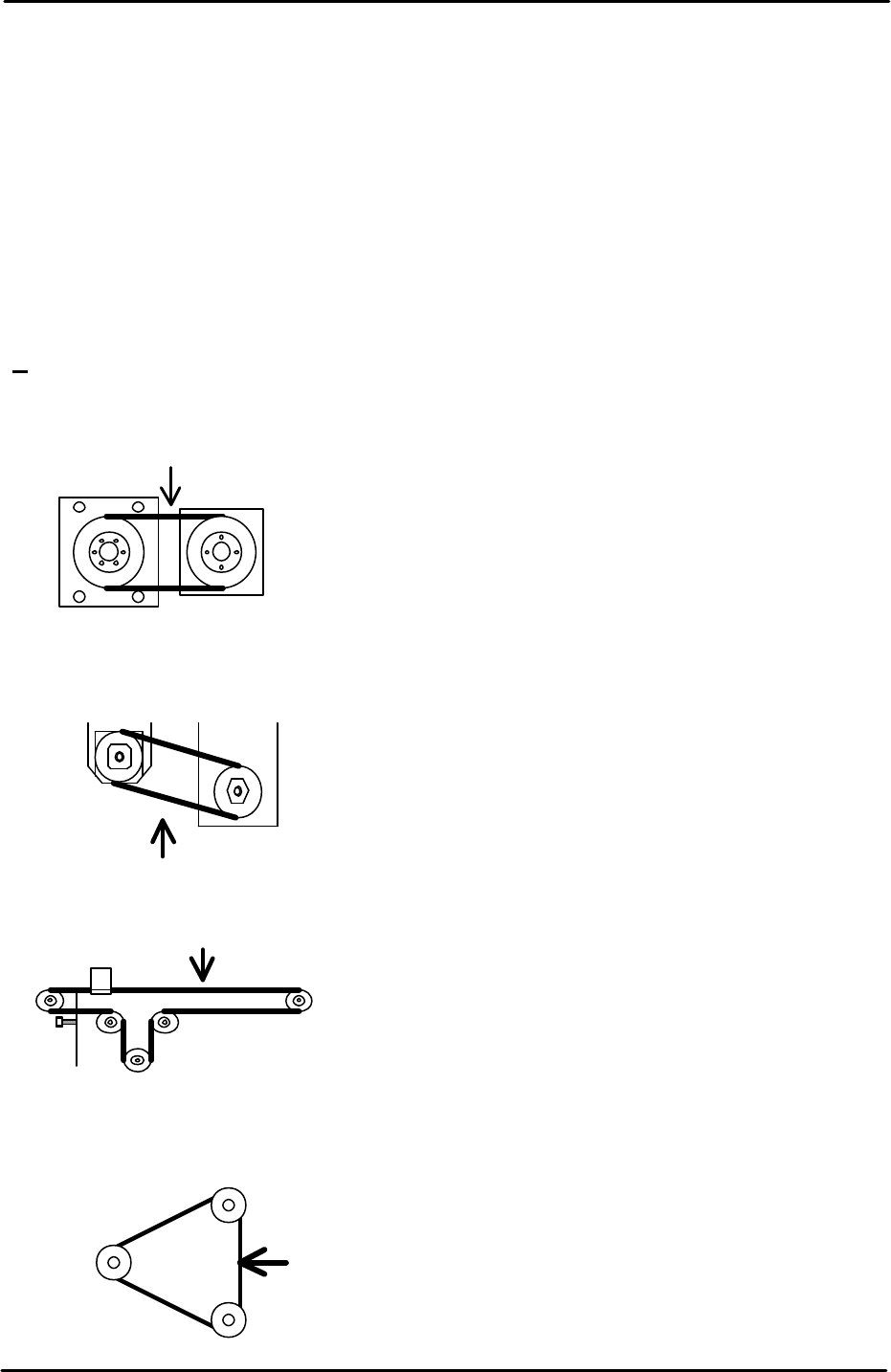
1.4 Belt tension measurement
• Measuring equipment: Tension meter (U-505)
1. Use tension meter (U-505) to check the belt tension of the Y, Z, T and U axes.
2. Move each of the axes to the Minus (-) mechanical stopper.
Note: make sure that the servo is OFF when moving the axes to the minus (-) mechanical
stoppers.
3. Refer to the following illustrations and check that the belt tension frequency for each axis
is within the specified range:
Y-axis measuring point
Tension meter setting
Belt unit amount: 0.4gf/mm Target Frequency
Belt width:15mm 165~183 Hz
Span length:130mm
U-axis measuring point
Tension meter setting
Belt unit amount: 0.25gf/mm Target Frequency
Belt width: 9mm 39~43Hz
Span length: 543mm
Z-axis measuring point
Tension meter setting
Belt unit amount: 0.25gf/mm Target Frequency
Belt width: 9mm 396~438Hz
Span length: 566mm
T-axis measuring point
Tension meter setting
Belt unit amount: 0.25gf/mm Target Frequency
Belt width: 15mm 140~154Hz
Span length: 151mm
Motor
Mid pulley
Ball screw

FK-9F98-29 XP Series Training Text for Service Engineers
Edition 5.0 XP241 – Chapter 1 Initial Adjustment Page 4 of 8
Fuji Machine Mfg. Co., Ltd. Okazaki.
SMT Equipment Quality Assurance Dept.
1 – 4 CS Section
1.5 Computer connection
MCS/X
1. Connect the LAN cable to the PC.
2. Remove the bottom left cover at the front of the machine, and connect the LAN cable to
the dedicated LAN port.
3. At the PC select [Start] – [Programs] – [MCSX] – [MCSX].
4. Click on the [File Manager] tab to bring up the "File Exchange" window.
5. To add a line, click on [Add Line], then enter a new line name, and click on [OK].
6. To add a machine, click on [Add M/C]:
Line Name: Choose an available line.
Machine nick name: For example XP241A
Machine type: Input the machine type.
IP Address: Input an IP address.
When finished click on [OK].
7. At the machine select [Maintenance B] – [Start Up Settings]:
Target: Input the "Machine nick name" registered in MCSX.
Ethernet Address: Input the same IP address as the one registered in MCSX.
Subnet Mask: If necessary input the subnet mask.
8. Click on the [Update] tab to save the new settings, then reboot the machine in order for
them to take effect.
9. Finally confirm that the PC and machine are communicating.
F4G
1. At the PC select [Start] – [Programs] – [Windows NT Explorer] – [Winnt] – [System
32] – [drivers] – [etc] – [hosts] and open the hosts file with notepad, a text file similar to
the one below will then open:
127.0.0.1 localhost
192.168.33.190 italy
192.168.39.2 pascal
192.168.39.10 uk
192.168.33.154 XP241A
Make a new entry, and in the first column input the machine's IP address, then a "host
name" in the next column. Close and save the file.
2. Select [Start] – [Programs] – [F4G] – [F4G] – [Line Config] and a text file will open. In
the MC Name column input the same hosts name as that registered in the hosts file, then
in the HOSTNAME column also input the same host name as that registered in the hosts
file, in this case XP241A. Under the MCTYPE column input the machine type, for