MIL- STD-883F 2004 TEST METHOD STANDARD MICROCIRCUITS.pdf - 第126页
MIL-STD-883F METHOD 1019.6 7 March 2003 10 FIGURE 1019-1. Flow diagram f or ionizing radiation test procedure for MO S and digital bipolar circuits. NO YES SELECT DO SE RATE SEE PARA. 3.6 IRRADIATE TO SPECIFI ED DOSE SEE…

MIL-STD-883F
METHOD 1019.6
7 March 2003
9
3.14 Test report
. As a minimum, the report shall include the device type number, serial number, the manufacturer,
package type, controlling specification, date code, and any other identifying numbers given by the manufacturer. The bias
circuit, parameter measurement circuits, the layout of the test apparatus with details of distances and materials used, and
electrical noise and current leakage of the electrical measurement system for in-flux testing shall be reported using drawings
or diagrams as appropriate. Each data sheet shall include the test date, the radiation source used, the bias conditions
during irradiation, the ambient temperature around the devices during irradiation and electrical testing, the duration of each
irradiation, the time between irradiation and the start of the electrical measurements, the duration of the electrical
measurements and the time to the next irradiation when step irradiations are used, the irradiation dose rate, electrical test
conditions, dosimetry system and procedures and the radiation test levels. The pre- and post-irradiation data shall be
recorded for each part and retained with the parent population data in accordance with the requirements of MIL-PRF-38535
or MIL-PRF-38534. Any anomalous incidents during the test shall be fully documented and reported. The accelerated
annealing procedure, if used, shall be described. Any other radiation test procedures or test data required for the delivery
shall be specified in the device specification, drawing or purchase order.
4. SUMMARY
. The following details shall be specified in the applicable acquisition document as required:
a. Device-type number(s), quantity, and governing specifications (see 3.1).
b. Radiation dosimetry requirements (see 3.3).
c. Radiation test levels including dose and dose rate (see 3.5 and 3.6).
d. Irradiation, electrical test and transport temperatures if other than as specified in 3.7.
e. Electrical parameters to be measured and device operating conditions during measurement (see 3.8).
f. Test conditions, i.e., in-flux or not-in-flux type tests (see 3.9).
g. Bias conditions for devices during irradiation (see 3.9.3).
h. Time intervals of the post-irradiation measurements (see 3.10).
i. Requirement for extended room temperature anneal test, if required (see 3.11).
j. Requirement for accelerated annealing test, if required (see 3.12).
k. Documentation required to be delivered with devices (see 3.14).
MIL-STD-883F
METHOD 1019.6
7 March 2003
10
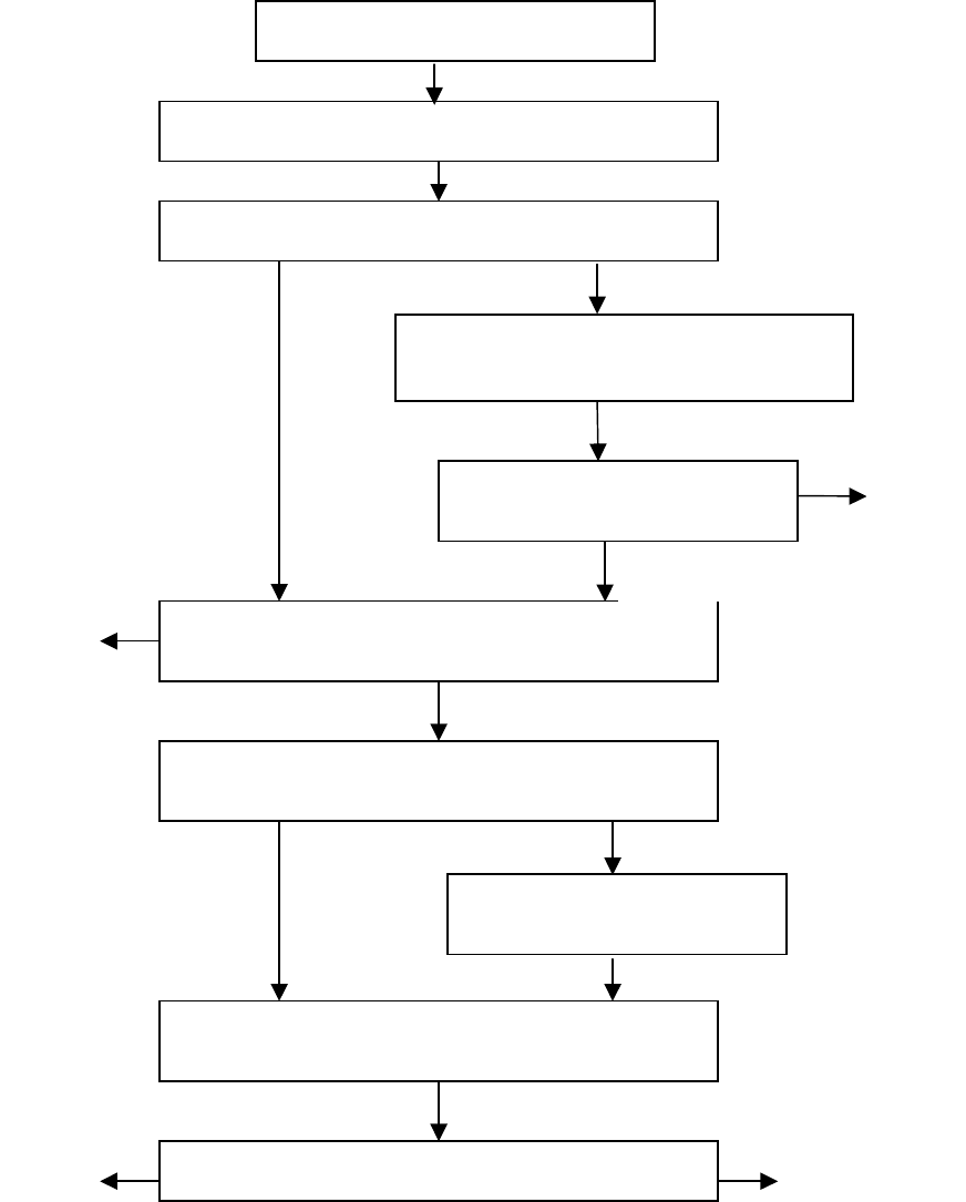
FIGURE 1019-1. Flow diagram for ionizing radiation test
procedure for MOS and digital bipolar circuits.
NO YES
SELECT DOSE RATE
SEE PARA. 3.6
IRRADIATE TO SPECIFIED DOSE
SEE PARA. 3.9
PERFORM SPECIFIED ELECTRICAL TESTS
SEE PARA. 3.8
DETERMINE IF EXTENDED ROOM TEMPER-
ATURE ANNEAL TEST IS REQUIRED
SEE PARA. 3.11.1
PERFORM SPECIFIED
ELECTRICAL TESTS
S
EE PARA. 3.8
DETERMINE IF ACCELERATED
ANNEALING TEST IS REQUIRED
SEE PARA.
3.12.1
DETERMINE IF 0.5X OVERTEST
IS REQUIRED
SEE PARA.
3.12.2.a.2
IRRADIATE AN ADDITIONAL 0.5 X
SPECIFIED DOSE
SEE PARA.
3.12.2.a
PERFORM ONE OF THREE ACCELERATED
ANNEALING PROCEDURES
SEE PARA.
3.12.2.b
PERFORM SPECIFIED ELECTRICAL TESTS
SEE PARA. 3.8
PASS
FAIL
FAIL
PASS
PASS
NO
YES
PASS FAIL
MIL-STD-883F
METHOD 1019.6
7 March 2003
11
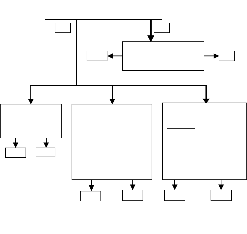
Figure 1019-
2. Flow diagram for ionizing radiation test procedure for bipolar (or BiCMOS) linear
or mixed-signal circuits
Determine the need for ELDRS testing
See Para. 3.13
No
Yes
Perform standard test
(Para 3.6.1 Condition A)
See Para 3.13.1
Pass Fail
Test at the intended
application dose rate
Para 3.6.3
Condition C
Perform low dose rate test
per Para 3.6.4, Condition D
1. ≤ 25 krad:
≤ 10 mrad/s
dose = 1.5 spec
2. >25 krad:
≥ 1000 hrs
dose = 2 spec
Perform elevated temperature
irradiation per Para 3.6.5,
Condition E
1. May be used if spec dose
≤ 50 krad
2. 0.5 to 5 rad/s, 100 ° C
3. Parameter design margin = 3
Pass
Pass
Fail
Pass Fail Fail