MIL- STD-883F 2004 TEST METHOD STANDARD MICROCIRCUITS.pdf - 第146页
MIL-STD-883F METHOD 1022 4 November 1980 2 3.2 p-c hannel devic es . 3.2.1 Tes t ci rcui t . The tes t ci rcui t shown on f igure 1022- 2 shall be assembl ed and the apparat us tur ned on. W ith the voltage s ources VS 1…
MIL-STD-883F
METHOD 1022
4 November 1980
1
METHOD 1022
MOSFET THRESHOLD VOLTAGE
1. PURPOSE
. This method establishes the means for measuring MOSFET threshold voltage. This method applies to
both enhancement-mode and depletion-mode MOSFETs, and for both silicon on sapphire (SOS) and bulk-silicon MOSFETs.
It is for use primarily in evaluating the response of MOSFETs to ionizing radiation, and for this reason the test differs from
conventional methods for measuring threshold voltage.
1.1 Definition
.
1.1.1 MOSFET threshold voltage, V
TH
. The gate-to-source voltage at which the drain current is reduced to the leakage
current, as determined by this method.
2. APPARATUS
. The apparatus shall consist of a suitable ammeter, voltmeters, and voltage sources. The apparatus
may be manually adjusted or, alternatively, may be digitally programmed or controlled by a computer. Such alternative
arrangements shall be capable of the same accuracy as specified below for manually adjusted apparatus.
2.1 Ammeter (A
1
). The ammeter shall be capable of measuring current in the range specified with a full scale accuracy of
±0.5 percent or better.
2.2 Voltmeters (V
1
and V
2
). The voltmeters shall have an input impedance of 10 MΩ or greater and have a capability of
measuring 0 to 20 V with a full scale accuracy of ±0.5 percent or better.
2.3 Voltage sources (VS
1
and VS
2
). The voltage sources shall be adjustable over a nominal range of 0 to 20 V, have a
capability of supplying output currents at least equal to the maximum rated drain current of the device to be tested, and have
noise and ripple outputs less than 0.5 percent of the output voltage.
3. PROCEDURE
.
NOTE: The absolute maximum values of power dissipation, drain voltage, drain current, or gate voltage specified in either
the applicable acquisition document or the manufacturer's specifications shall not be exceeded under any circumstances.
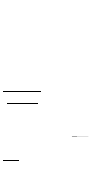
3.1 N-channel devices
.
3.1.1 Test circuit
. The test circuit shown on figure 1022-1 shall be assembled and the apparatus turned on. With the
voltage sources VS
1
and VS
2
set to 0 volts, the MOSFET to be tested shall be inserted into the test circuit. The gate polarity
switch shall be set to the appropriate position, and voltage source VS
1
shall be set 1.0 V negative with respect to the
anticipated value of threshold voltage V
TH
. Voltage source VS
2
shall be adjusted until voltmeter V
2
indicates the specified
drain voltage V
D
. The current I
D
, indicated by ammeter A
1
, and the gate voltage V
G
, indicated by voltmeter V
1
, shall be
measured and recorded.
3.1.2 Measurement of gate voltages
. The measurement shall be repeated at gate voltages which are successively 0.25
volts more positive until either the maximum gate voltage or maximum drain current is reached. If the gate voltage reaches
0 volts before either of these limits has been reached, the gate polarity switch shall be changed as necessary and
measurements shall continue to be made at gate voltages which are successively 0.25 volts more positive until one of these
limits has been reached.
*
*
MIL-STD-883F
METHOD 1022
4 November 1980
2
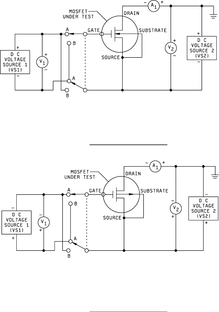
3.2 p-channel devices
.
3.2.1 Test circuit
. The test circuit shown on figure 1022-2 shall be assembled and the apparatus turned on. With the
voltage sources VS
1
and VS
2
set to 0 volts, the MOSFET to be tested shall be inserted into the test circuit. The gate polarity
switch shall be set to the appropriate position, and voltage source VS
1
shall be set 1.0 V positive with respect to the
anticipated value of threshold voltage V
TH
. Voltage source VS
2
shall be adjusted until voltmeter V
2
indicates the specified
drain voltage V
D
. The current I
D
, indicated by ammeter A
1
, and the gate voltage V
G
, indicated by voltmeter V
1
, shall be
measured and recorded.
3.2.2 Measurement of gate voltages
. The measurement shall be repeated at gate voltages which are successively 0.25
volts more negative until either the maximum gate voltage or maximum drain current is reached. If the gate voltage reaches
0 volts before either of these limits has been reached, the gate polarity switch shall be changed as necessary and
measurements shall continue to be made at gate voltages which are successively 0.25 volts more negative until one of
these limits has been reached.
3.3 Leakage current
. The leakage current shall be measured.
3.3.1 Drain voltage
. The drain voltage shall be the value specified in 4b.
3.3.2 Gate voltage
. The gate voltage shall be five volts different from the anticipated threshold voltage in the direction of
reduced drain current.
3.4 Plot of gate voltage
. The gate voltage, V
G
, shall be plotted versus the square-root of the drain
current minus the leakage current, √ I
D
- I
L
. At the point of maximum slope, a straight line shall be extrapolated downward.
The threshold voltage V
TH
is the intersection of this line with the gate voltage axis. Examples are shown on figure 1022-3.
3.5 Report
. As a minimum, the report shall include the device identification, the test date, the test operator, the test
temperature, the drain voltage, the range of gate voltage, the leakage current, and the threshold voltage.
4. SUMMARY
. The following details shall be specified in the applicable acquisition document:
a. Test temperature. Unless otherwise specified, the test shall be performed at ambient.
b. Drain voltage.
c. Maximum drain current.
d. Range of gate voltage.
MIL-STD-883F
METHOD 1022
4 November 1980
3
NOTES: Gate polarity switch set at A for enhancement mode, B for depletion mode.
FIGURE 1022-1. Test circuit for n-channel MOSFETs
.
NOTE: Gate polarity switch set at A for enhancement mode, B for depletion mode.
FIGURE 1022-2. Test circuit for p-channel MOSFETs
.