MIL- STD-883F 2004 TEST METHOD STANDARD MICROCIRCUITS.pdf - 第147页
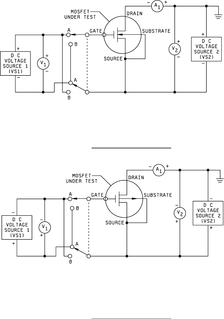
MIL-STD-883F METHOD 1022 4 November 1980 3 NOTES: Gate polar ity s witc h set at A for enhanc ement mode, B f or depleti on mode. FIGURE 1022-1. Test c irc uit for n-channel MOSFETs . NOTE: Gate polar ity s witc h set at…

MIL-STD-883F
METHOD 1022
4 November 1980
2
3.2 p-channel devices
.
3.2.1 Test circuit
. The test circuit shown on figure 1022-2 shall be assembled and the apparatus turned on. With the
voltage sources VS
1
and VS
2
set to 0 volts, the MOSFET to be tested shall be inserted into the test circuit. The gate polarity
switch shall be set to the appropriate position, and voltage source VS
1
shall be set 1.0 V positive with respect to the
anticipated value of threshold voltage V
TH
. Voltage source VS
2
shall be adjusted until voltmeter V
2
indicates the specified
drain voltage V
D
. The current I
D
, indicated by ammeter A
1
, and the gate voltage V
G
, indicated by voltmeter V
1
, shall be
measured and recorded.
3.2.2 Measurement of gate voltages
. The measurement shall be repeated at gate voltages which are successively 0.25
volts more negative until either the maximum gate voltage or maximum drain current is reached. If the gate voltage reaches
0 volts before either of these limits has been reached, the gate polarity switch shall be changed as necessary and
measurements shall continue to be made at gate voltages which are successively 0.25 volts more negative until one of
these limits has been reached.
3.3 Leakage current
. The leakage current shall be measured.
3.3.1 Drain voltage
. The drain voltage shall be the value specified in 4b.
3.3.2 Gate voltage
. The gate voltage shall be five volts different from the anticipated threshold voltage in the direction of
reduced drain current.
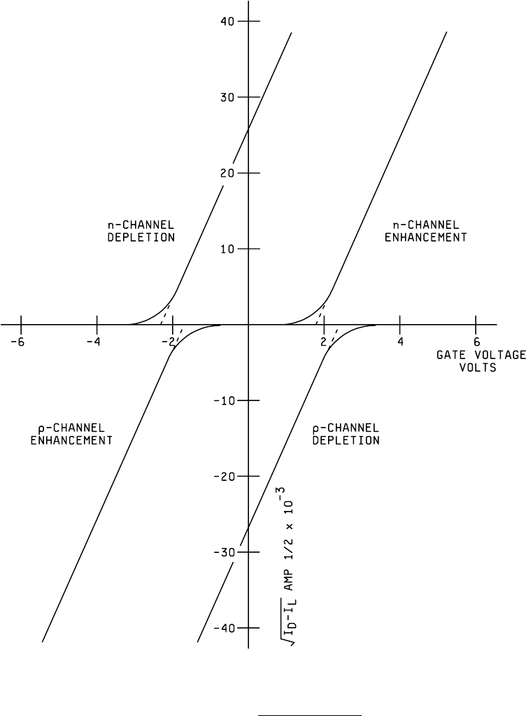
3.4 Plot of gate voltage
. The gate voltage, V
G
, shall be plotted versus the square-root of the drain
current minus the leakage current, √ I
D
- I
L
. At the point of maximum slope, a straight line shall be extrapolated downward.
The threshold voltage V
TH
is the intersection of this line with the gate voltage axis. Examples are shown on figure 1022-3.
3.5 Report
. As a minimum, the report shall include the device identification, the test date, the test operator, the test
temperature, the drain voltage, the range of gate voltage, the leakage current, and the threshold voltage.
4. SUMMARY
. The following details shall be specified in the applicable acquisition document:
a. Test temperature. Unless otherwise specified, the test shall be performed at ambient.
b. Drain voltage.
c. Maximum drain current.
d. Range of gate voltage.
MIL-STD-883F
METHOD 1022
4 November 1980
3
NOTES: Gate polarity switch set at A for enhancement mode, B for depletion mode.
FIGURE 1022-1. Test circuit for n-channel MOSFETs
.
NOTE: Gate polarity switch set at A for enhancement mode, B for depletion mode.
FIGURE 1022-2. Test circuit for p-channel MOSFETs
.
MIL-STD-883F
METHOD 1022
4 November 1980
4
FIGURE 1022-3. Examples of curves
.