MIL- STD-883F 2004 TEST METHOD STANDARD MICROCIRCUITS.pdf - 第149页
MIL-STD-883F METHOD 1023.2 19 August 1994 1 METHOD 1023.2 Dose Rate Res ponse and Thres hold for Upset of Linear Microc irc uits 1. PUR POSE . This test procedur e defines the requi rements for meas uring t he dose rat e…
MIL-STD-883F
METHOD 1022
4 November 1980
4
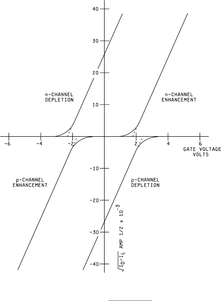
FIGURE 1022-3. Examples of curves
.

MIL-STD-883F
METHOD 1023.2
19 August 1994
1
METHOD 1023.2
Dose Rate Response and Threshold for Upset
of Linear Microcircuits
1. PURPOSE
. This test procedure defines the requirements for measuring the dose rate response and upset threshold
of packaged devices containing analog functions when exposed to radiation from a flash X-ray source or from a linear
accelerator. This procedure addresses the measurement of dose rate response characteristics of a linear circuit, excluding
latchup which is addressed in MIL-STD-883 Test Method 1020.
1.1 Definitions
. The following are the definitions of terms used in this method:
a. Dose rate response
. The transient changes which occur in the operating parameters or in the output signal of an
operating linear microcircuit when exposed to a pulse of ionizing radiation.
b. Dose rate
. Energy absorbed per unit time and per unit mass by a given material from the radiation field to which it
is exposed. Units are specified in Gray (Gy) per second (s) in the material of interest, e.g., Gy(Si)/s, Gy(SiO
2
)/s,
Gy(GaAs)/s, etc.
c. Dose rate induced upset
. An upset has occurred when the radiation induced transient change in a specified
parameter (e.g., in output voltage, supply current, output signal waveform) exceeds a predetermined level.
d. Upset threshold
. The upset threshold is the minimum dose rate at which the device upsets. However, the
reported measured upset threshold shall be the maximum dose rate at which the device does not upset and which
the transient disturbance of the output waveform and/or supply current remains within the specified limits.
1.2 Test plan
. Prior to dose rate testing, a test plan shall be prepared which describes the radiation source, the
dosimetry techniques, test equipment, the device to be tested, test conditions, and any unique testing considerations. A
detailed procedure for each device type to be tested shall be prepared, either as part of the test plan, or in separate test
procedure documents. The procedure shall include bias conditions, test sequence, schematics of the test setup and specific
functions to be tested. The test plan shall be approved by the acquiring activity, and as a minimum, the items listed below
shall be provided in the test plan or procedure:
a. Device types, including package types, manufacturer, date codes, and quantities to be tested.
b. Traceability requirements, such as requirements for serialization, wafer or lot traceability, etc.
c. Requirements for data reporting and submission.
d. Block diagram or schematic representation of test set up.
e. List of equipment used in the testing and calibration compliance requirements as required.
f. Test conditions, e.g., bias voltage, temperature, etc.
g. Electrical parameters to be monitored and device operating conditions, including functional test requirements
before, during and after the radiation pulse. Test patterns to be used for devices with storage elements, or
devices with input pattern sensitivity shall also be specified.
h. Group A electrical test requirements for pre- and post-dose rate testing, when applicable, to include test limits and
failure criteria.
i. Radiation test parameters such as pulse width(s), radiation dose(s) per pulse and dose rate range(s).
j. Total ionizing dose limit acceptable for each device type.
k. Upset and failure criteria, e.g., effective number of bits (ENOB) or missing codes in analog to digital converters
(ADCs), delta VOH or Vref, time to recovery, output waveform distortion in shape or frequency, etc.

MIL-STD-883F
METHOD 1023.2
19 August 1994
2
1.3 Formulation of the upset criteria
. The upset criteria are usually generated from characterization data at the dose rate
of interest. Upset criteria can sometimes be determined by analysis/simulation (SPICE or equivalent computer code) of the
application circuit, if the code has been verified to agree with experimental data for similar circuits and exposure conditions.
1.4 Specification of the
upset criteria. Once formulated, the upset criteria shall be specified in the detailed specification.
The upset criteria may consist of the following (a waveform may be included denoting the acceptable boundaries):
a. Measurement circuit to which criteria apply.
b. Peak amplitude of tolerable transient change in output voltage.
c. Allowable duration of transient output change (recovery time).
d. Limiting value for the surge in power supply current and recovery characteristics.
e. Steady state (return to normalcy) level of the output voltage following recovery.
f. ENOB or missing codes for ADCs.
g. Delta parameters such as Vref or VOH.
h. Device saturation time.
2. APPARATUS
. The apparatus shall consist of the radiation source, dosimetry equipment, remote test circuit to include
signal recording devices, cabling, line drivers, interconnect fixture, and exposure board. Adequate precautions shall be
observed to obtain an electrical measurement system with sufficient insulation, ample shielding, satisfactory grounding and
low noise from electrical interference or from the radiation environment (see section 3.7.3).
2.1 Radiation Source
. Either of two radiation sources shall be used for dose rate testing: 1) a flash x-ray machine
(FXR), or 2) an electron linear accelerator (LINAC). The FXR shall be used in the x-ray mode and the LINAC in the electron
(e-beam) mode. Unless otherwise specified, the FXR peak charging voltage shall be 2 MV or greater, and the LINAC beam
energy shall be 10 MeV or greater. The uniformity of the radiation field in the device irradiation volume shall be +
15% as
measured by the dosimetry system. The dose per radiation exposure shall be as specified in the test plan or procedure.
2.2 Dosimetry System
. A dosimetry system shall be used which provides a measurement accuracy within + 15 percent.
A calibrated PIN diode may be used to obtain both the shape of the radiation pulse and the dose. The following American
Society for Testing and Materials (ASTM) standards or their equivalent may be used:
ASTM E 526 Standard Method for Measuring Dose for Use in Linear Accelerator Pulsed Radiation Effects Tests.
ASTM E 666 Standard Method for Calculation of Absorbed Dose from Gamma or X Radiation.
ASTM E 668 Standard Practice for the Application of Thermo-luminescence Dosimetry (TLD) Systems for Determining
Absorbed Dose in Radiation Hardness Testing of Electronic Devices.
These methods describe techniques to determine the absorbed dose in the material of interest. Device packaging material
and thickness should be considered in determining the dose to the DUT. For FXR tests, dose enhancement effects of the
package shall be considered. Dosimetry techniques shall be reported in the test report as well as device packaging
material, thickness and dose enhancement effects, if applicable.