MIL- STD-883F 2004 TEST METHOD STANDARD MICROCIRCUITS.pdf - 第155页
MIL-STD-883F METHOD 1023.2 19 August 1994 7 APPENDIX A A1. This appendix provides an example of the spec ifi cati on of tes t detai ls f or an operat ional ampli fier . Becaus e the tes t condit ions depend bot h on the …

MIL-STD-883F
METHOD 1023.2
19 August 1994
6
4. Test Report
. A dose rate test report shall be prepared and shall include the following (as a minimum):
a. Device identification, including manufacturer, wafer lot and/or inspection lot traceability information, pre-radiation
history (e.g., class level S, class level B, prototype, etc).
b. Radiation test facility, type of source, pulse width, dosimetry data including pulse waveform.
c. Test date, test operator's name and organization.
d. Results of the noise test.
e. Device response data, listed by device serial number, including output and supply recovery waveforms, and dose
per pulse for each device.
f. Power supply droop during pulse.
g. Post-exposure functional test data if applicable.
h. All information included in the test plan/procedure (may be referenced or appended to test report), and any
deviations from the approved test plan/procedure.
i. Package material and thickness, and effect of package material on dose to the device (see paragraph 2.2).
5. SUMMARY
. The applicable device specification or drawing shall specify the following (as applicable):
a. Device types and quantities to be tested.
b. Traceability (device number, wafer/lot number, etc.) requirements and requirements for data reporting and
submission.
c. Electrical configuration of the DUT during exposure (include schematic of exposure configuration).
d. Sequence of exposure conditions and logical test patterns.
e. Outputs to be monitored and recorded.
f. Dose rate level(s) and pulse width(s).
g. Criteria for upset and recovery, steady state value of recovered outputs and/or supply current. Include sample
waveforms if necessary.
h. Upset threshold and failure level (if applicable).
i. Post exposure functional test necessary to verify the stored pattern, and maximum time interval between
application of the radiation pulse and start of functional test.
j. Total ionizing dose limit and burnout level for each device type.
k. Maximum current limiting resistance in series with the power supply in the application (if applicable), and
allowable resistance in the test circuit (paragraph 2.3.5).
l. Requirements for Group A electrical testing pre- and post-radiation testing, if applicable.
m. Test instrument requirements, if other than those indicated above.
n. Requirements for characterization, recharacterization and analysis.

MIL-STD-883F
METHOD 1023.2
19 August 1994
7
APPENDIX A
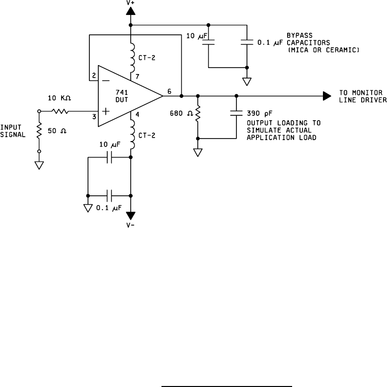
A1. This appendix provides an example of the specification of test details for an operational amplifier. Because the test
conditions depend both on the type of device and on the specific application, this example shall not be considered as
suitable for use in any given case. It is provided only as an illustration of the use of this test method.
A2. Test specification, method 1023:
a. Type 741 operational amplifier, in 8-pin TO-5 package.
b. Test circuit as given on figure 1023-1. Leave pins 1, 5, and 8 unconnected.
c. V+=9.0 +
0.2 V; V-=-9.0 + 0.2 V; input signal 280 mV +5% peak to peak, 2000 +50 Hz.
d. Monitor pin 6 and the power supply current.
e. Standard noise limits apply.
f. Pulse width: 20 ns (Full width half maximum).
g. Total Ionizing dose shall not exceed 10 Gy(Si).
h. Test at a dose rate of 10
5
+
30% Gy(Si)/s.
i. Test temperature shall be ambient (25° +
5°C).
j. Pass/Fail Criteria: Power supply currents and the output signal shall return to within 10% of the
pre-rad levels within 1 ms of the radiation pulse.
k. This test is considered a destructive test.
MIL-STD-883F
METHOD 1023.2
19 August 1994
8
FIGURE 1023-1. Example of test circuit for OP-AMP
.