MIL- STD-883F 2004 TEST METHOD STANDARD MICROCIRCUITS.pdf - 第157页
MIL-STD-883F METHOD 1023.2 19 August 1994 9 APPENDIX B B1. This appendix provides an example of the spec ifi cati on of tes t detai ls f or an analog to di gital convert er (ADC) . Because t he test condit ions depend bo…
MIL-STD-883F
METHOD 1023.2
19 August 1994
8
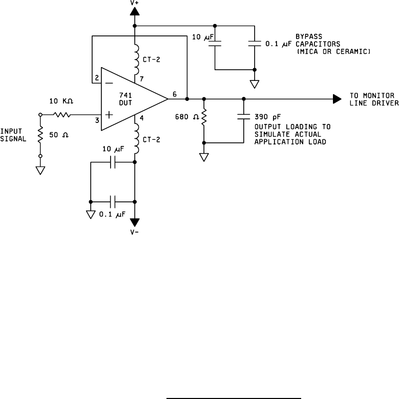
FIGURE 1023-1. Example of test circuit for OP-AMP
.

MIL-STD-883F
METHOD 1023.2
19 August 1994
9
APPENDIX B
B1. This appendix provides an example of the specification of test details for an analog to digital converter (ADC).
Because the test conditions depend both on the type of device and on the specific application, this example shall not be
considered as suitable for use in any given case. It is provided only as an illustration of the use of this test method.
B2. Test specification, method 1023:
a. Type ADC (n=# bits=12), 40 pin ceramic DIP.
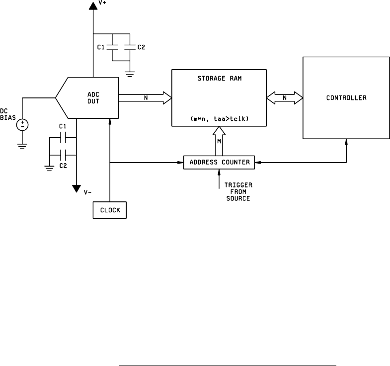
b. The test circuit is given in Figure 1023-2, and an overview of the test setup is provided in Figure 1023-3.
The storage RAM must write at a speed (taa>tclk) exceeding the DUT clock frequency, and provide an interface to
the controller, and be capable of storing a trigger pulse from the radiation source. Note that if the data ready line of
the ADC is used, it must be monitored separately, as it may also upset.
c. A minimum of 3 input voltages shall be tested. Adjust input bias to center output code on:
1. Midscale (2
n
/2)
2. Fullscale - 10% (2
n
-0.1*2
n
)
3. Zero + 10% (0+0.1*2
n
)
d. As a minimum, perform tests at 10 MHz and 1 MHz (Fmax and 0.1*Fmax).
e. Upset Criteria: Determination of the upset threshold shall be determined by statistical analysis comparing the pre-
shot ADC output codes with the data taken during and immediately after the shot. The time to recover (within
20%) shall also be determined by comparing the pre-rad data with the post-rad data.
f. Pulse width: 20 ns (Full width half maximum).
g. Test at dose rates ranging from 10
2
- 10
7
Gy(Si)/s to establish upset threshold.
h. Total ionizing dose shall not exceed 500 Gy(Si).
i. Test at ambient temperature (25° +
5°C).
j. After completion of the upset tests, test up to the machine maximum dose rate to determine if devices burn out.
This test is a destructive test.
MIL-STD-883F
METHOD 1023.2
19 August 1994
10
FIGURE 1023-2. Example of test circuit for ADC (C1 = 4.7 µF, C2 = 0.1 µF)
.