MIL- STD-883F 2004 TEST METHOD STANDARD MICROCIRCUITS.pdf - 第16页
MIL-STD-883F 10 FIGURE 1a. Or ientati on of mic roelec tronic device t o FIGURE 1b. Radial lead fl at pack ages . directio n of ap plied force . FIGURE 1c. Dual-in- line pac kage . FIGURE 1d. Fl at pack age with r adial …

MIL-STD-883F
9
4.1.2 Revisions
. Revisions are numbered consecutively using a period to separate the test method number and the
revision number. For example, 4001.1 is the first revision of test method 4001.
4.1.3 Method of reference
. When applicable, test methods contained herein shall be referenced in the individual
specification by specifying this standard, the method number, and the details required in the summary paragraph of the
applicable method. To avoid the necessity for changing specifications which refer to this standard, the revision number
should not be used when referencing test methods. For example, use 4001, not 4001.1.
4.2 Test results
. The data resulting from application of any test method or procedure shall be reported in terms of the
actual test conditions and results. "Equivalent" results (e.g., equivalent 25°C device hours or failure rate derived from 125°C
test conditions) may be reported in addition to the actual results but shall not be acceptable as an alternative to actual
results. Results of any test method or procedure shall be accompanied by information on the total quantity of devices in
each lot being tested on a 100 percent or sampling basis, the associated quantity of devices in the sample for tests on a
sampling basis, and the number of failures or devices rejected by test method and observed mode of failure. In cases
where more than a single device type (part number) is involved in the makeup of a lot for inspection or delivery, the data
shall be reported as above but with a further breakdown by part number.
4.3 Test sample disposition
. Test sample disposition shall be in accordance with A.4.3.2.1 of Appendix A of MIL-PRF-
38535.
4.4 Orientation
.
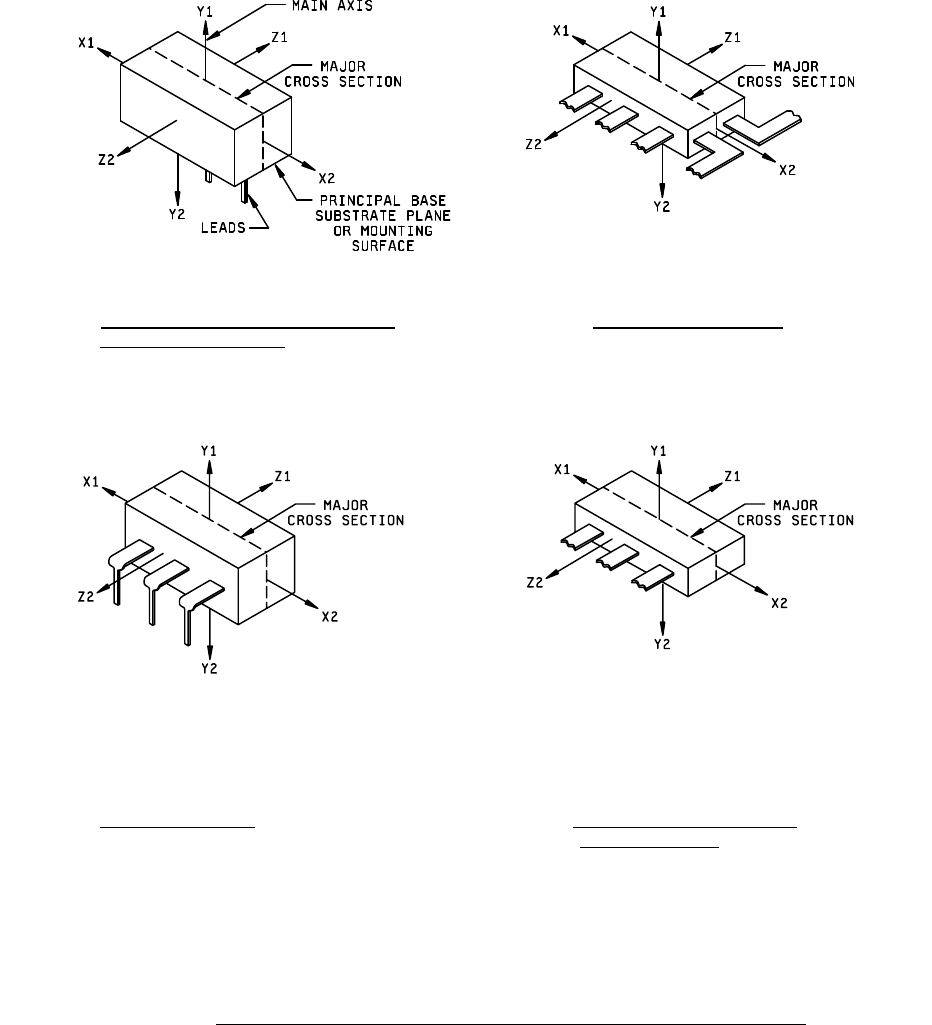
4.4.1 Identification of orientation and direction of forces applied
. For those test methods which involve observation or the
application of external forces which must be related to the orientation of the device, such orientation and direction of forces
applied shall be identified in accordance with figures 1 and 2.
4.4.2 Orientation for other case configurations
. For case configurations other than those shown in figures 1 and 2, the
orientation of the device shall be as specified in the applicable acquisition document.
4.4.3 Orientation for packages with different size lateral dimensions
. In flat packages where radial leads emanate from
three or more sides, the X-direction shall be assigned to the larger and the Z-direction to the smaller of the two lateral
dimensions.
*
MIL-STD-883F
10
FIGURE 1a. Orientation of microelectronic device to
FIGURE 1b. Radial lead flat packages.
direction of applied force
.
FIGURE 1c. Dual-in-line package
. FIGURE 1d. Flat package with radial leads
from one side only
.
FIGURE 1. Orientation noncylindrical microelectronic devices to direction of applied forces
.
MIL-STD-883F
11
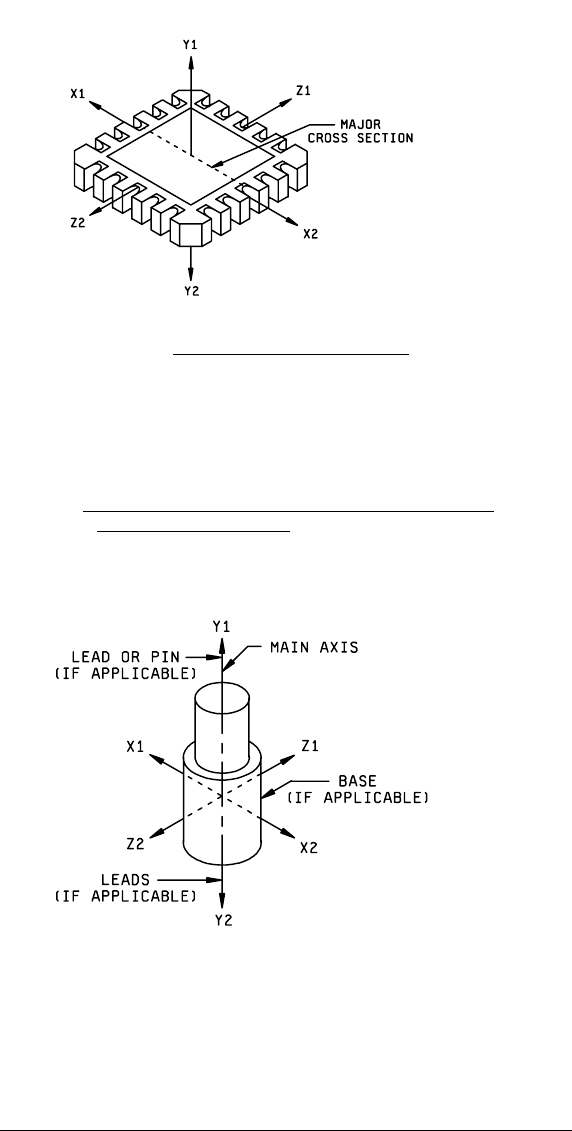
FIGURE 1e. Leadless chip carrier (top view)
.
NOTE: The Y1 force application is such that it will tend to lift the die off the substrate or
the wires off the die. The reference to applied force actually refers to the force which
operates on the device itself an may be the resultant of the primary forces applied in a
different manner or direction to achieve the desired stress at the device (e.g., constant
acceleration).
FIGURE 1. Orientation of noncylindrical microelectronic devices to
direction of applied forces
- Continued.
NOTE: The Y1 force application is such that it will tend to lift the die off the substrate or
the wires off the die. The reference to applied force actually refers to the force which
operates on the device itself and may be the resultant of the primary forces applied in a
different manner or direction to achieve the desired stress at the device (e.g., constant
acceleration).
FIGURE 2. Orientation of cylindrical microelectronic device to direction of applied forces
.