MIL- STD-883F 2004 TEST METHOD STANDARD MICROCIRCUITS.pdf - 第166页
MIL-STD-883F METHOD 1031 25 August 1983 2 3.1.1. 2 Long term t esti ng . For l ong term r eliabil ity as suranc e tes ting the f ollowi ng modific ations shall be made: St ep AB Inc reased t o 12 hours. St ep CD Incr eas…

MIL-STD-883F
METHOD 1031
25 August 1983
1
METHOD 1031
THIN FILM CORROSION TEST
1. PURPOSE
. The thin film corrosion test is performed for the purpose of demonstrating the quality or reliability of
devices subjected to the specified conditions over a specified time period. This sample test is to be applied as either a short
term specialized quality assurance test or as a long term acceleration test to assure device reliability. It is particularly suited
to devices containing thin film conductors, resistors, or fuses which are susceptible to corrosion as a result of cavity water
vapor which is less than the limits specified in methods 5005 herein and MIL-PRF-38534. Because of the destructive nature
of the test, it should not be used as a 100 percent screen. It is the intent of this test to reveal time and temperature, stress
dependent, moisture related failure modes resulting from metallization corrosion.
2. APPARATUS
. Suitable sockets or other mounting means shall be provided to make firm electrical contact to the
terminals of devices under test in the specified circuit configuration. Power supplies and a temperature chamber shall be
capable of maintaining the specified operating conditions as a minima throughout the testing period. The test chamber shall
be conditioned with dry air to prevent the test ambient from reaching 100 percent relative humidity during temperature
cycling.
3. PROCEDURE
. The microcircuits shall be subjected to the specified conditions, duration, and temperature, and the
required measurements shall be made at the conclusion of the test. The test conditions, duration, quantity, and temperature
shall be recorded and shall govern for the entire test. All programmable devices processed by the manufacturer to an
altered item drawing shall be programmed prior to the test.
3.1 Test conditions
.
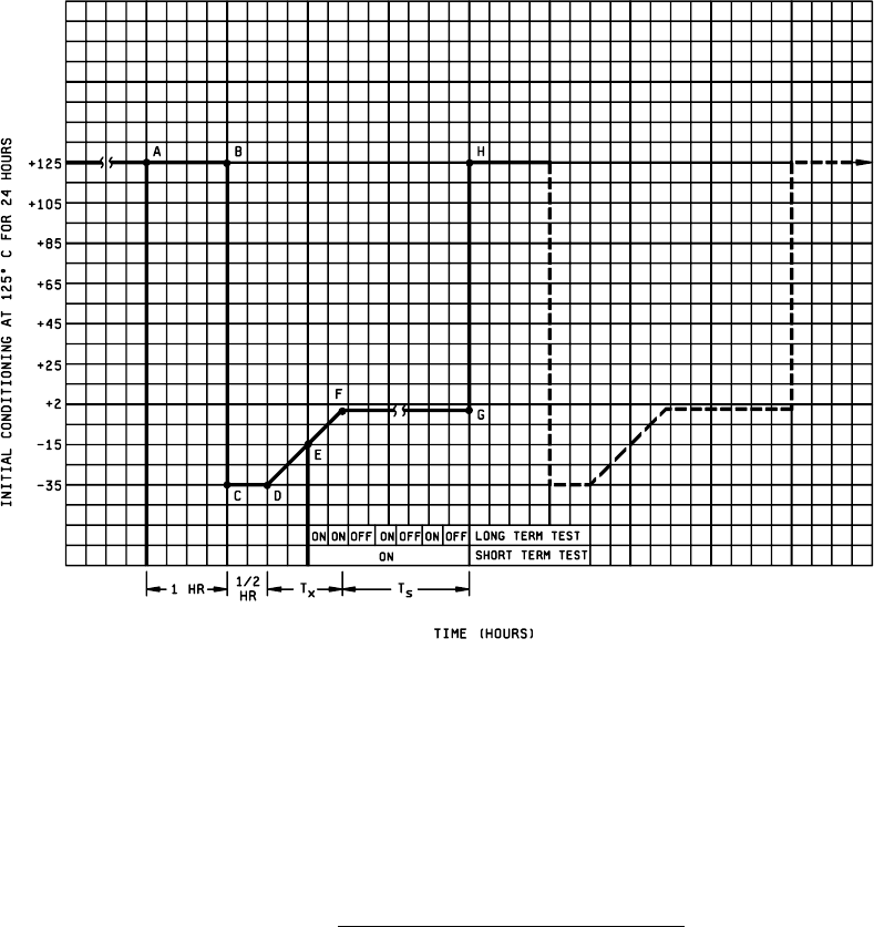
3.1.1 Device conditioning
. All devices shall be conditioned, without bias at 125°C ±10°C for a minimum of 24 hours
before proceeding with the test.
3.1.1.1 Short term testing
. For short term quality assurance testing the time-temperature bias sequence of figure 1031-1
shall be followed for 16 cycles, 3 hours each, for a total of 48 hours. The following sequence shall be used for the short
term test:
Initial conditioning drives out deeply trapped water into ambient
Step AB 125°C: Activate surface water from walls.
Step BC Freeze out ambient water on walls and chip (temperature ramp 100°C/minute).
Step CD Allow surface temperatures inside package to come to equilibrium (i.e., redistribute water).
Step DE Transfer water from walls to chip (cold surface pump). At point E apply bias while chip is wet.
Step EF Adjust temperature ramp so that chip is always the coldest temperature by minimizing heat
dissipation and adjusting temperature ramp (maximum 100°C/minute).
Step FG Maintain 2°C ambient to insure highest R.H. near chip while bias is still applied.
Step GH Heat quickly to evaporate water from walls, possibly with explosive force to enhance
contaminant transfer from the walls to the chip (maximum 100°C/minute).
Temperature test cycle at 25°C when bias is applied. Remove from test fixture.

MIL-STD-883F
METHOD 1031
25 August 1983
2
3.1.1.2 Long term testing
. For long term reliability assurance testing the following modifications shall be made:
Step AB Increased to 12 hours.
Step CD Increased to 1 hour.
Step DE Remains the same one-half hour.
Step EG Bias applied at pt E and then cycled 30 minutes on, 30 minutes off during FG. Total time 24
hours.
Step EF May be extended to 4 hours if power dissipation can be minimized.
Step FG Increased to 6.5 hours. Total test time 10 weeks or 70 cycles.
Terminate test cycle at 25°C when bias is applied.
Remove from test fixture.
3.2 Measurements
. Unless otherwise specified, all electrical measurement shall be completed within 12 hours after
removal from the specified test conditions. End point measurements shall consist of group A, subgroups 1 and 7 at 25°C.
NOTE: Method 1014 fine and gross leak test must be accomplished before 3.1.1 and after 3.2. Any circuit failing the leak
test will be removed from the test lot.
4. SUMMARY
. The following details shall be provided in the applicable device specification or drawing:
a. The electrical test configuration.
b. The number of devices to be tested and the acceptance criteria.
c. Requirements for data recording, when applicable.
MIL-STD-883F
METHOD 1031
25 August 1983
3
FIGURE 1031-1. Graphical representation of corrosion test
.