MIL- STD-883F 2004 TEST METHOD STANDARD MICROCIRCUITS.pdf - 第17页
MIL-STD-883F 11 FIGURE 1e. Leadles s c hip car rier ( top view) . NOTE : The Y1 force applica tion is such that it will t end to lift the die of f the s ubstr ate or the wir es off the die. The r eferenc e to appli ed fo…
MIL-STD-883F
10
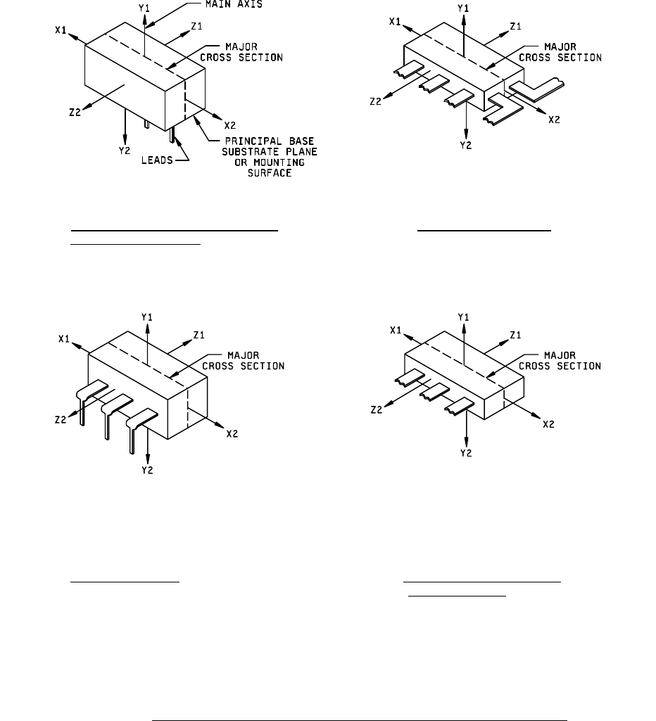
FIGURE 1a. Orientation of microelectronic device to
FIGURE 1b. Radial lead flat packages.
direction of applied force
.
FIGURE 1c. Dual-in-line package
. FIGURE 1d. Flat package with radial leads
from one side only
.
FIGURE 1. Orientation noncylindrical microelectronic devices to direction of applied forces
.
MIL-STD-883F
11
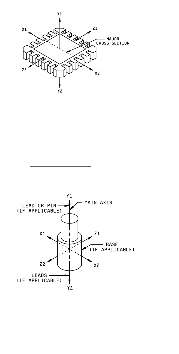
FIGURE 1e. Leadless chip carrier (top view)
.
NOTE: The Y1 force application is such that it will tend to lift the die off the substrate or
the wires off the die. The reference to applied force actually refers to the force which
operates on the device itself an may be the resultant of the primary forces applied in a
different manner or direction to achieve the desired stress at the device (e.g., constant
acceleration).
FIGURE 1. Orientation of noncylindrical microelectronic devices to
direction of applied forces
- Continued.
NOTE: The Y1 force application is such that it will tend to lift the die off the substrate or
the wires off the die. The reference to applied force actually refers to the force which
operates on the device itself and may be the resultant of the primary forces applied in a
different manner or direction to achieve the desired stress at the device (e.g., constant
acceleration).
FIGURE 2. Orientation of cylindrical microelectronic device to direction of applied forces
.

MIL-STD-883F
12
4.5 Test conditions
. All newly designed device types shall meet the test conditions specified in 4.5.1 through 4.5.3.2.
4.5.1 Calibration requirements
. Calibration shall be applied to those items of measuring and test equipment used to
assure product delivery specifications or critical manufacturing elements. Calibration shall be performed in accordance with
the requirements of ANSI/NCSL Z540-1 or equivalent. Calibrated items shall be controlled, used and stored in a manner
suitable to protect calibration integrity. Test equipment requiring calibration (single items or assemblages) shall be identified
and labeled in accordance with ANSI/NCSL Z540-1 or equivalent.
4.5.2 Electrical test equipment accuracy
. Unless otherwise specified in the acquisition document, test conditions such
as: voltage, resistive loads, capacitive loads, input switching parameters, input static parameters, currents and others shall
be set to nominal values as defined in the acquisition document, with tolerances suitable for the test in which they are used.
4.5.3 Electrical test equipment capability
. Using any or all of the following techniques, the manufacturer shall determine
that the test set/system is suitable to ensure product conformance with the acquisition document. Alternate suitable
techniques may be used when approved by the qualifying activity. The manufacturer shall define and document methods
used. The test equipment accuracy should be better than the allowable device tolerance in accordance with the following
ratios:
a. Greater than or equal to 10:1 for routine processes.
b. Greater than or equal to 4:1 for special processes (commercial equipment not readily available).
NOTE: State of the art requirements in which 4:1 can not be effectively achieved due to a lack of national standards shall
be justified and documented.
4.5.3.1 Control based on uncertainty
. Test processes that have complex characteristics are best performed and
controlled by the application of uncertainty analysis. The overall uncertainty in a test or measurement process shall be
determined and the impact of said uncertainty on the product parameter tolerance shall be taken into account. The methods
used for determining uncertainty shall be defined and documented. The method selected may use any (or combinations) of
the following forms:
a. Arithmetic addition (linear), normally produces an overly conservative estimate and reflects a highly improbable
situation in which contributing errors are at their maximum limit at the same time and same direction.
b. Root Sum Square (RSS), normally applied where the errors tend to fit a normal distribution (gaussian) and are from
independent sources.
c. Partial Derivatives, used where complex relationships exist.
d. Monte Carlo Simulation, used in very complex situations where other methods are not easily applied or do not fit.
e. SRM (or controlled correlation device) testing providing observable data.
NOTE: Observable data, from a controlled device, may be relied upon to provide feedback that confirms process
performance is within statistical limits.
f. Analysis of systematic and random errors, applying corrections as applicable.
g. Any other recognized method of combining errors into an expression of uncertainty substantiated by an engineering
analysis.
4.5.3.2 Use and control of correlation devices/SRM's
. When a manufacturer elects to use correlation devices or SRM's,
methods of use and control shall be in place and documented including parameters, type, quantity, description,
identification, storage, handling and periodic verification requirements.