MIL- STD-883F 2004 TEST METHOD STANDARD MICROCIRCUITS.pdf - 第190页
MIL-STD-883F METHOD 2004.5 29 November 1985 4 TEST CONDITION C 1 - LEAD TORQUE 1. PURPOSE . This test is des igned to c heck device l eads (or termi nals) and seal s for their resi stanc e to twi sti ng motion s. 2. APPA…
MIL-STD-883F
METHOD 2004.5
29 November 1985
3
TEST CONDITION B
2
- LEAD FATIGUE
1. PURPOSE
. This test is designed to check the resistance of the leads to metal fatigue.
2. APPARATUS
. Attaching devices, clamps, supports, or other suitable hardware necessary to apply a repeated bending
stress through the specified bend angle.
3. PROCEDURE
. The appropriate procedure of 3.1 or 3.2 for the device under test shall be used.
3.1 Procedure for dual-in-line packages
. The leads to be tested shall be subjected to three cycles of test condition B
1
and
shall be subjected to a force sufficient to bend the leads as specified in 3.4 of condition B
1
.
3.2 Procedure for flat packages and can packages
. A force of 0.229 ±0.014 kg (8 ±0.5 ounces), unless otherwise specified,
shall be applied to each lead to be tested for three 90° ±5° arcs of the case. For leads with a preplated or prefinished section
modulus equal to or less than that of a rectangular lead with a cross section of 0.16 x 0.51 mm (0.006 x 0.020 inches) or round
leads with a cross section of 0.51 mm (0.020 inch) in diameter, the force shall be 0.085 ±0.009 kg (3 ±0.3 ounces). Section
modulus is defined as bc
2
/6 for rectangular leads, and 0.098 (φb
1
)
3
for round leads (see MIL-STD-1835). An arc is defined as
the movement of the case, without torsion, to a position perpendicular to the pull axis and return to normal. All arcs on a single
lead shall be made in the same direction and in the same plane without lead restriction. A bending cycle shall be completed in
from 2 to 5 seconds. For devices with rectangular or ribbon leads, the plane of the arcs shall be perpendicular to the flat plane
of the lead. The test shall not be applied to end leads of packages where its application will apply primarily torsion forces at the
lead seal.
3.2.1 Optional procedure for fine pitch/small leads
. A force as determined by the following formula unless otherwise
specified, shall be applied to each lead to be tested for 90 degrees ±5 degree arcs of the device. All other conditions of section
3.2 shall apply: Weight = (area in square inches) x 2.1 % x (K psi) x 453.6 grams/lb. Where K is based on the ultimate tensile
strength (UTS) for a particular material. Typical value for kovar and alloy 42 are listed below. The UTS for other materials can
be found in vendor data sheets. The result shall be rounded to the nearest whole number.
NOTE: A lead pitch of less than or equal to 25 mils is considered fine pitch.
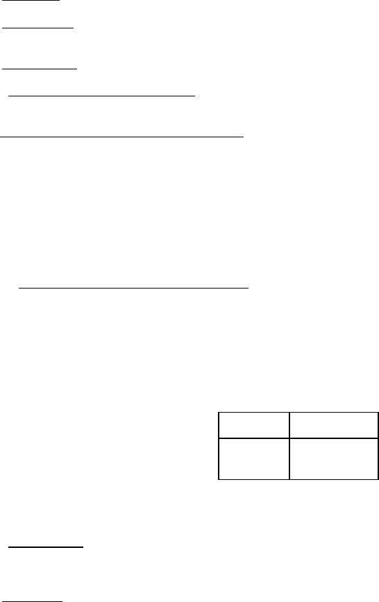
Material
UTS in psi
Kovar
Alloy 42
75000
71000
3.3 Failure criteria
. A broken lead on a device shall be considered a failure. When examined using magnification between
10X and 20X after removal of the stress, any device which exhibits any evidence of breakage, loosening, or relative motion
between the terminal lead and the device body shall be considered a device failure.
4. SUMMARY
. The following details shall be specified in the applicable acquisition document:
a. Force to be applied to the lead, if other than above (see 3).
b. Number of cycles, if other than above (see 3).
c. Maximum bend angle, if other than above (see 3).

MIL-STD-883F
METHOD 2004.5
29 November 1985
4
TEST CONDITION C
1
- LEAD TORQUE
1. PURPOSE
. This test is designed to check device leads (or terminals) and seals for their resistance to twisting
motions.
2. APPARATUS
. The torque test requires suitable clamps and fixtures, and a torsion wrench or other suitable method of
applying the specified torque without lead restriction.
3. PROCEDURE
. The appropriate procedure of 3.1 or 3.2 for the device under test shall be used.
3.1 Procedure for devices with circular cross-section terminals or leads
. The device body shall be rigidly held and the
specified torque shall be applied for 15 seconds minimum to the lead (terminal) to be tested, without shock, about the axis of
the lead (terminal).
3.2 Procedure for devices with rectangular cross-section terminals or leads
. The device body shall be rigidly held and a
torque of 1.45 ±.145 kg-mm (2.0 ±0.2 ounce-inch) unless otherwise specified, shall be applied to the lead (terminal) at a
distance of 3.05 ±0.76 mm (0.12 ±0.03 inch) from the device body or at the end of the lead if it is shorter than 3.05 mm (0.12
inch). The torque shall be applied about the axis of the lead once in each direction (clockwise and counterclockwise).
When devices have leads which are formed close to the body, the torque may be applied 3.05 ±0.76 mm (0.12 ±0.03 inch)
from the form. For device leads which twist noticeably when less than the specified torque is applied, the twist shall be
continued until the twist angle reaches 30° ±10° or the specified torque is achieved, whichever condition occurs first. The
lead shall then be restored to its original position.
3.3 Failure criteria
. When examined using magnification between 10X and 20X after removal of the stress, any evidence
of breakage, loosening, or relative motion between the terminal (lead) and the device body shall be considered a device
failure. When a seal test in accordance with method 1014 is conducted as a post test measurement following the lead
integrity test(s), meniscus cracks shall not be cause for rejection of devices which pass the seal test.
4. SUMMARY
. The following details shall be specified in the applicable acquisition document:
a. Torque to be applied for circular cross-section leads (see 3.1).
b. Duration of torque application for circular cross-section leads, if other than 15 seconds minimum (see 3.1).
c. Torque to be applied for rectangular cross-section leads, if other than 1.45 ±0.145 kg-mm (2.0 ±0.2 ounce-inch)
(see 3.2).
d. See general summary above.
TEST CONDITION C
2
- STUD TORQUE
1. PURPOSE
. This test is designed to check the resistance of the device with threaded mounting stud to the stress
caused by tightening the device when mounting.
2. APPARATUS
. The torque test requires suitable clamps and fixtures, and a torsion wrench or suitable method of
applying the specified torque.
3. PROCEDURE
. The device shall be clamped by its body or flange. A flat steel washer of a thickness equal to six
thread pitches of the stud being tested and a new class 2 fit steel nut shall be assembled in that order on the stud, with all
parts clean and dry. The specified torque shall be applied without shock to the nut for the specified period of time. The nut
and washer shall then be disassembled from the device, and the device then examined for compliance with the
requirements.

MIL-STD-883F
METHOD 2004.5
29 November 1985
5
3.1 Failure criteria
. The device shall be considered a failure if any of the following occurs:
a. The stud breaks or is elongated greater than one-half of the thread pitch.
b. It fails the specified post-test end point measurements.
c. There is evidence of thread stripping or deformation of the mounting seat.
4. SUMMARY
. The following details shall be specified in the applicable acquisition document:
a. The amount of torque to be applied (see 3).
b. Length of time torque is to be applied (see 3).
c. Measurements to be made after test (see 3).
TEST CONDITION D - SOLDER PAD ADHESION FOR LEADLESS CHIP CARRIER AND SIMILAR DEVICES
1. PURPOSE
. This test is designed to check the capabilities of the device solder pads to withstand a delamination (peel)
stress of specified tension and time.
2. APPARATUS
. Equipment for 10X magnification, suitable clamps and fixtures for securing the device and applying the
specified tension/time conditions to wires soldered to the device solder pads. Equivalent linear pull test equipment may be
used.
3. PROCEDURE
. Unless otherwise specified, a delamination (peel) stress test shall be applied to randomly selected
solder pads from each device selected for test. Further, unless otherwise specified, the sampling shall be Sample Size
Number = 15, c = 0 based on the number of solder pads tested, chosen from a minimum of three devices. Preparation and
testing of devices shall be in accordance with figure 2004-2 of this method and as follows.
a. Pretinned soft annealed solid copper wire of a gauge (diameter) nearest, but not exceeding that of the nominal
solder pad width, shall be soldered using Sn60A or Pb40A or Sn63A or Pb37A of ANSI/J-STD-006 (previously
known as Sn60 or Sn63 solder in accordance with QQ-S-571) to each solder pad to be tested in a manner such
that the wire is bonded over the entire solder pad length and terminates at the package edge (see figure 2004-2).
The unsoldered portion of the wire shall be bent perpendicular to the bond plane prior to attachment. Caution
should be taken to assure that the solder pad metallization is not damaged during the soldering or the wire
bending operation.
b. Unless otherwise specified, a minimum tension of 8 ounces (2.22 N) shall be applied, without shock, to each
solder pad to be tested in a direction perpendicular to the solder pad surface and maintained for 30 seconds
minimum.
3.1 Failure criteria
. When examined, using 10X magnification, after removal of the tension stress, the appearance of any
delamination involving constituent solder pad interfaces shall be considered an adhesion failure of the solder pad.
Separation of the solder pad from the device is an obvious (without visual magnification) adhesion failure. Separation of the
wire from the solder fillet (leaving the solder pad intact) or wire breakage is considered a test procedure failure.
4. SUMMARY
. The following details shall be specified in the applicable acquisition document:
a. Sampling criteria, if other than specified (see 3.1).
b. Failure criteria, if other than specified (see 3.1).
c. Tension to be applied in this test if other than 8 ounces (2.22 N).
d. Length of time tension is to be applied if other than 30 seconds.