MIL- STD-883F 2004 TEST METHOD STANDARD MICROCIRCUITS.pdf - 第205页
MIL-STD-883F METHOD 2009.9 19 August 1994 3 FIGURE 2009-1. Castell ation t o solder pad mi sali gnment . d. Castel lati on configur ation not in acc ordanc e with the f ollowi ng (see f igure 2009- 2). The c astel lati o…

MIL-STD-883F
METHOD 2009.9
19 August 1994
2
3.3.4 Package Body/Lid Finish
a. Defective finish (peeling, flaking, pitting, blistering, or corrosion). Discoloration that does not exhibit these
conditions is acceptable.
b. Scratches, mars, or indentations, either due to damage or processing, that expose base metal. Exposed
underplate is acceptable.
3.3.5 Leads
a. Broken leads.
b. Leads or terminals that are not intact or aligned in their normal location, free of sharp or unspecified lead bends, or
twisted more than 20° from the normal lead plane.
c. Leads with pits and/or depressions that exceed 25% of the width (diameter for round leads) and are greater than
50% of the lead thickness in depth.
d. Leads with burrs exceeding a height greater than 50% of the lead thickness.
e. Lead misalignment to the braze pad to the extent that less than 75% of the lead braze section is brazed to the pad.
f. Metallization (including solder lead finish) in which the isolation between leads or between lead and other package
metallization is reduced to less than 50% of lead separation (pad separation for brazed leads) but in no case less
than the case outline minimum.
g. Braze material that increases the lead dimensions to greater than 1.5 times the lead thickness above the design
maximum between the seating plane and the ceramic body or that increases the lead dimensions to greater than
the design maximum below the seating plane.
h. Scratches that expose base metal over more than 5% of the lead surface area. Exposed base metal on the cut
lead ends is acceptable and does not count in the 5%.
3.3.6 Package body/lid - leaded devices
a. Broken packages or cracks in the packages. Surface scratches shall not be cause for failure except where they
violate other criteria stated herein for marking, finish, etc.
b. Any chipout dimension that exceeds 0.060 inch in any direction on the surface and has a depth that exceeds 25%
of the thickness of the affected package element (e.g., cover, base, or wall).
c. External lead metallization stripe forming a conductor to a brazed lead that exhibits voids greater than 25% of the
conductor width.
d. Evidence of cracks, delamination, separation, or voiding on any multilayer ceramic package.
3.3.7 Package body/lid - leadless devices
a. Ceramic chip-outs that dimensionally exceed 50% of the distance between terminals in any direction on the
affected surface (edge or corner), and exceed a depth of 25% of the thickness of the affected package element
(e.g., cover, lid, base, or wall).
b. Evidence of cracks, delamination, separation, or voiding on any package element.
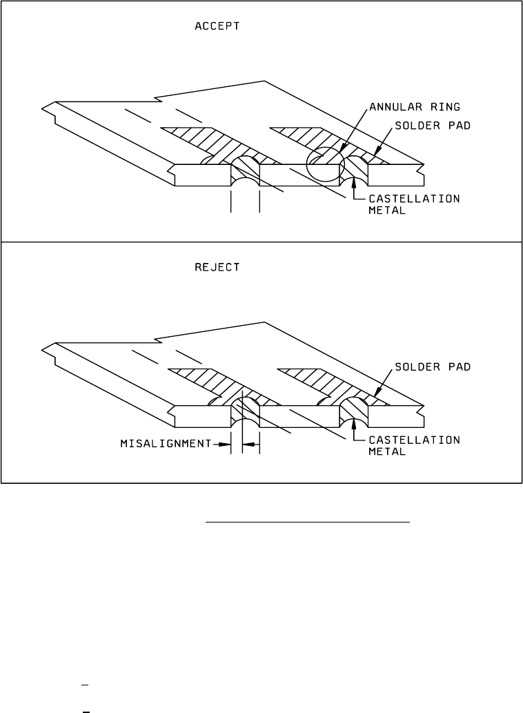
c. Castellation to solder pad misalignment. The metal in the castellation, exclusive of the angular ring, shall be within
the visually extended boundaries of the solder pad (see figure 2009-1).
MIL-STD-883F
METHOD 2009.9
19 August 1994
3
FIGURE 2009-1. Castellation to solder pad misalignment
.
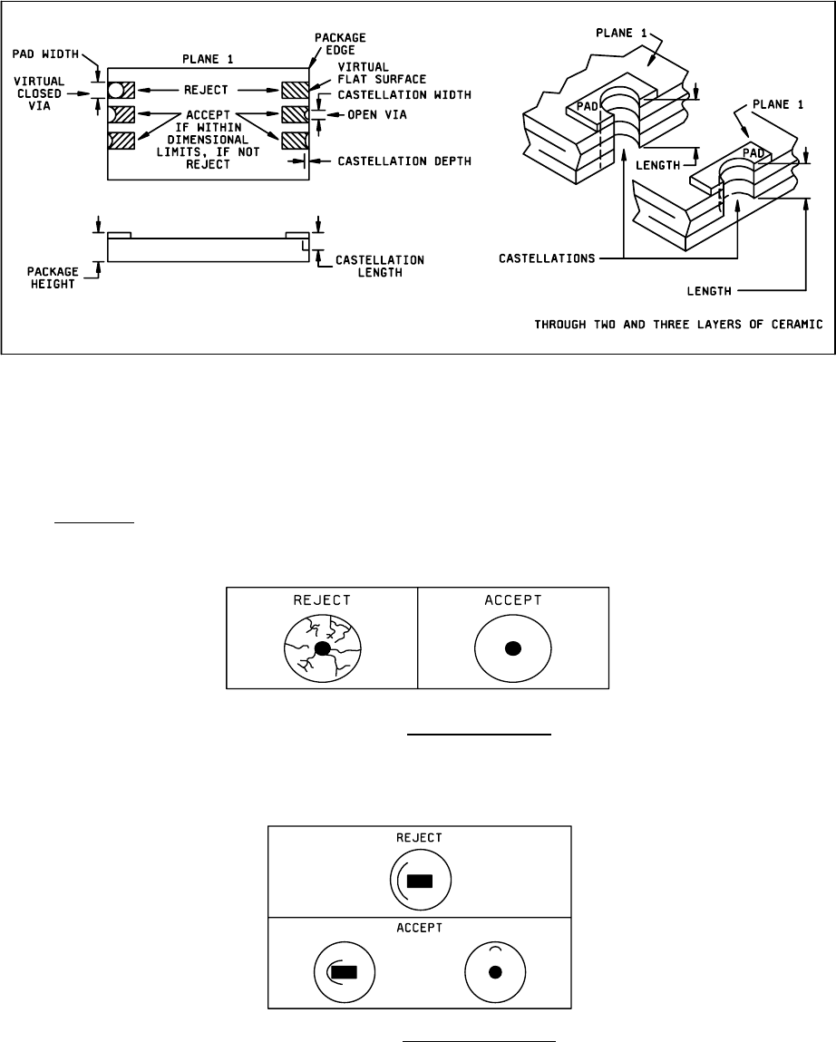
d. Castellation configuration not in accordance with the following (see figure 2009-2). The castellation shall be
roughly concave, confined by a 3-dimensional space traversing all castellated ceramic layers at the package edge.
The surface of the castellation may be irregular. The “3-dimensional space" has these dimensions:
1. Minimum width >1/3 package terminal pad width.
2. Minimum depth > 1/2 castellation minimum width.
3. Length = as designed (see figure 2009-2).
4. Maximum width <
package terminal pad width.
5. Maximum depth <
1/2 castellation maximum width.
These dimensions are an attempt to ensure with some reasonableness that the castellations are not viewed, in the extreme
sense, as virtual flat surfaces on the package edge and are not virtual closed vias (holes).
MIL-STD-883F
METHOD 2009.9
19 August 1994
4
NOTE: Ceramic layers shift, edges are rough after punching, plating buildup is not smooth etc., all of these combine
during package manufacture to make the castellation measurement difficult. Therefore, in the event of conflicts in
determining castellation acceptance, direct contact measurement shall be made using the limits specified in
MIL-STD-1835.
FIGURE 2009-2. Castellation requirements
3.3.8 Glass seals
.
a. Crazing of the glass seal surface (see figure 2009-3).
FIGURE 2009-3. Crazed glass surface
.
b. Any single circumferential crack (or overlapping crack) that does not lie completely within a single quadrant (i.e.,
extends beyond 90° arc or rotation about the lead), and extends beyond or is located in the region beyond the
midpoint of distance from the lead to the case (see Figure 2009-4).
FIGURE 2009-4. Circumferential cracks
.