MIL- STD-883F 2004 TEST METHOD STANDARD MICROCIRCUITS.pdf - 第206页
MIL-STD-883F METHOD 2009.9 19 August 1994 4 NOTE : Cerami c layers sh ift, edges are rough af ter punc hing, plat ing buil dup is not smooth et c., all of these c ombine during pac kage manufac ture t o make the c astel …
MIL-STD-883F
METHOD 2009.9
19 August 1994
3
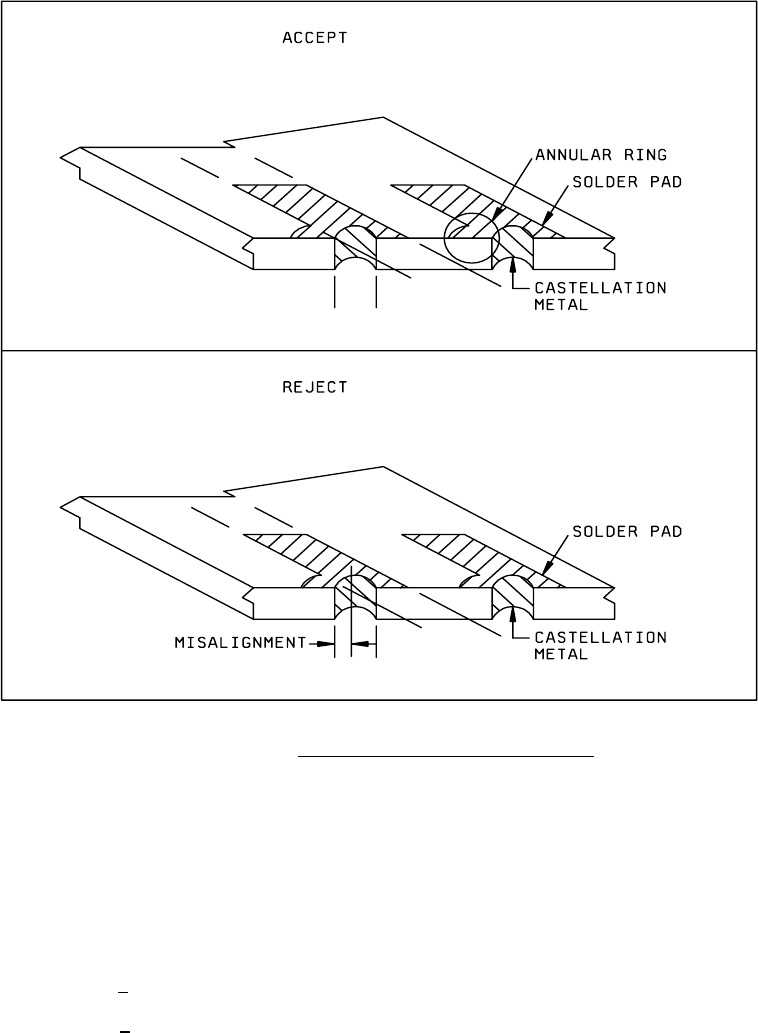
FIGURE 2009-1. Castellation to solder pad misalignment
.
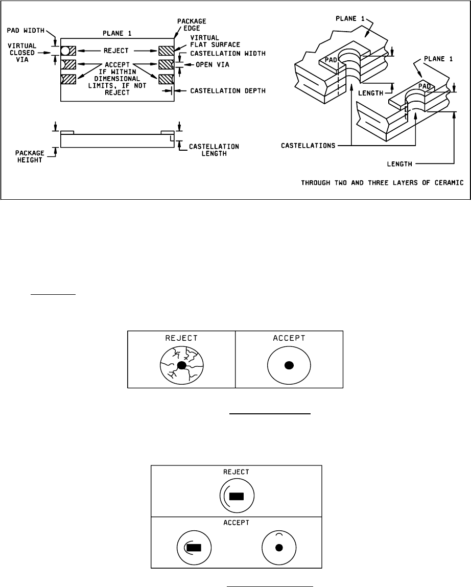
d. Castellation configuration not in accordance with the following (see figure 2009-2). The castellation shall be
roughly concave, confined by a 3-dimensional space traversing all castellated ceramic layers at the package edge.
The surface of the castellation may be irregular. The “3-dimensional space" has these dimensions:
1. Minimum width >1/3 package terminal pad width.
2. Minimum depth > 1/2 castellation minimum width.
3. Length = as designed (see figure 2009-2).
4. Maximum width <
package terminal pad width.
5. Maximum depth <
1/2 castellation maximum width.
These dimensions are an attempt to ensure with some reasonableness that the castellations are not viewed, in the extreme
sense, as virtual flat surfaces on the package edge and are not virtual closed vias (holes).
MIL-STD-883F
METHOD 2009.9
19 August 1994
4
NOTE: Ceramic layers shift, edges are rough after punching, plating buildup is not smooth etc., all of these combine
during package manufacture to make the castellation measurement difficult. Therefore, in the event of conflicts in
determining castellation acceptance, direct contact measurement shall be made using the limits specified in
MIL-STD-1835.
FIGURE 2009-2. Castellation requirements
3.3.8 Glass seals
.
a. Crazing of the glass seal surface (see figure 2009-3).
FIGURE 2009-3. Crazed glass surface
.
b. Any single circumferential crack (or overlapping crack) that does not lie completely within a single quadrant (i.e.,
extends beyond 90° arc or rotation about the lead), and extends beyond or is located in the region beyond the
midpoint of distance from the lead to the case (see Figure 2009-4).
FIGURE 2009-4. Circumferential cracks
.
MIL-STD-883F
METHOD 2009.9
19 August 1994
5
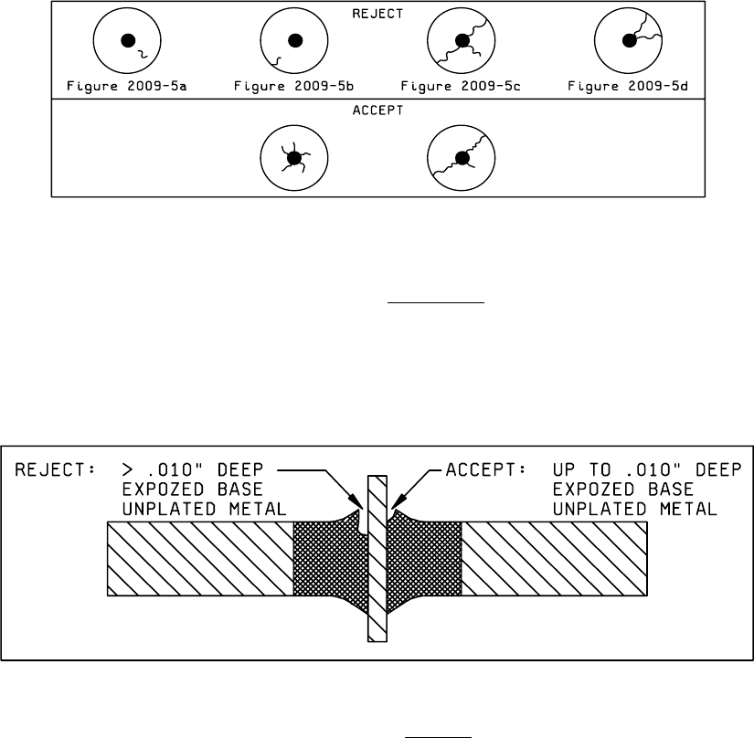
c. Radial cracks that exhibit the following:
1. Cracks that do not originate at the lead (see figures 2009-5a and 2009-5b).
2. Three or more cracks that extend beyond the midpoints of distance from the lead to the case (see figure
2009-5c).
3. Two cracks that extend beyond the midpoint of the distance from the lead to the case and that lie within the same
quadrant (see figure 2009-5d).
FIGURE 2009-5. Radial Cracks
.
d. Any chip-out that penetrates the sealing glass deeper than the glass meniscus plane. The glass meniscus is
defined as that area of glass that wicks up the lead or terminal. Exposed base metal as a result of meniscus chip
outs is acceptable, provided that the exposed area is no deeper than 0.010 inch (see figure 2009-6).
FIGURE 2009-6. Chip-outs
.