MIL- STD-883F 2004 TEST METHOD STANDARD MICROCIRCUITS.pdf - 第207页
MIL-STD-883F METHOD 2009.9 19 August 1994 5 c. Ra dial cracks th at ex hibit th e followin g: 1. Cracks th at do n ot origin ate at th e l ead (see f igures 2009-5a and 2009-5b) . 2. Three o r more cracks th at ex t end …
MIL-STD-883F
METHOD 2009.9
19 August 1994
4
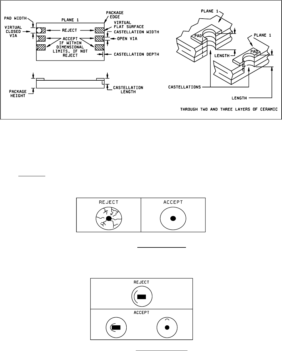
NOTE: Ceramic layers shift, edges are rough after punching, plating buildup is not smooth etc., all of these combine
during package manufacture to make the castellation measurement difficult. Therefore, in the event of conflicts in
determining castellation acceptance, direct contact measurement shall be made using the limits specified in
MIL-STD-1835.
FIGURE 2009-2. Castellation requirements
3.3.8 Glass seals
.
a. Crazing of the glass seal surface (see figure 2009-3).
FIGURE 2009-3. Crazed glass surface
.
b. Any single circumferential crack (or overlapping crack) that does not lie completely within a single quadrant (i.e.,
extends beyond 90° arc or rotation about the lead), and extends beyond or is located in the region beyond the
midpoint of distance from the lead to the case (see Figure 2009-4).
FIGURE 2009-4. Circumferential cracks
.
MIL-STD-883F
METHOD 2009.9
19 August 1994
5
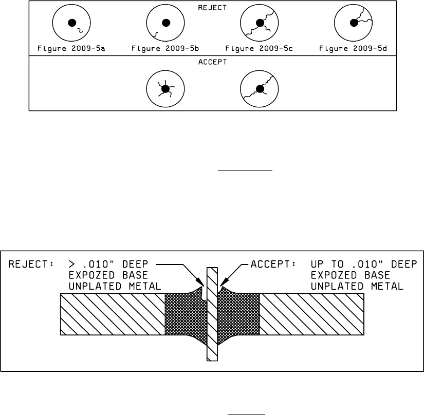
c. Radial cracks that exhibit the following:
1. Cracks that do not originate at the lead (see figures 2009-5a and 2009-5b).
2. Three or more cracks that extend beyond the midpoints of distance from the lead to the case (see figure
2009-5c).
3. Two cracks that extend beyond the midpoint of the distance from the lead to the case and that lie within the same
quadrant (see figure 2009-5d).
FIGURE 2009-5. Radial Cracks
.
d. Any chip-out that penetrates the sealing glass deeper than the glass meniscus plane. The glass meniscus is
defined as that area of glass that wicks up the lead or terminal. Exposed base metal as a result of meniscus chip
outs is acceptable, provided that the exposed area is no deeper than 0.010 inch (see figure 2009-6).
FIGURE 2009-6. Chip-outs
.
MIL-STD-883F
METHOD 2009.9
19 August 1994
6
FIGURE 2009-7a. Surface bubbles
. FIGURE 2009-7b. Subsurface bubbles.
e. Surface bubbles that exceed the following:
1. Open bubbles in the glass seal that exceed 5 mils in diameter (see Figure 2009-7a). For packages with a glass-
filled header (i.e., TO-5), open bubbles that exceed 10 mils diameter, or an open bubble that exceeds 5 mils
diameter situated closer than 10 mils to a lead.
2. Open bubbles in strings or clusters that exceed 2/3 of the distance between the lead and the package wall.
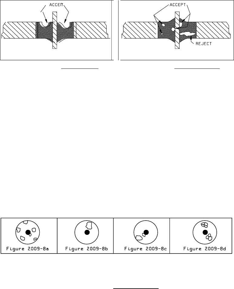
f. Subsurface bubbles that exceed the following:
1. Large bubbles or voids that exceed 1/3 of the glass sealing area (see Figure 2009-8a).
2. Single bubble or void that is larger than 2/3 of the distance between the lead and the package wall at the site of
inclusion (see Figures 2009-7b and 2009-8b).
3. Two bubbles in a line totaling more than 2/3 distance from pin to case (see Figure 2009-8c).
4. Interconnecting bubbles greater than 2/3 the distance between pin and case (see Figure 2009-8d).
FIGURE 2009-8. Subsurface bubbles
.
g. Reentrant seals that exhibit non-uniform wicking (i.e., negative meniscus) at the lead and/or body interface (see
Figure 2009-9).