MIL- STD-883F 2004 TEST METHOD STANDARD MICROCIRCUITS.pdf - 第244页
MIL-STD-883F METHOD 2010.11 18 June 2004 34 Condition A Conditi on B Class le vel S Class lev el B e. Trim pa th into th e metalliz ation e xce pt block re sistors. NOTE: This cri teri a can be excluded f or tri m paths …
MIL-STD-883F
METHOD 2010.11
18 June 2004
33
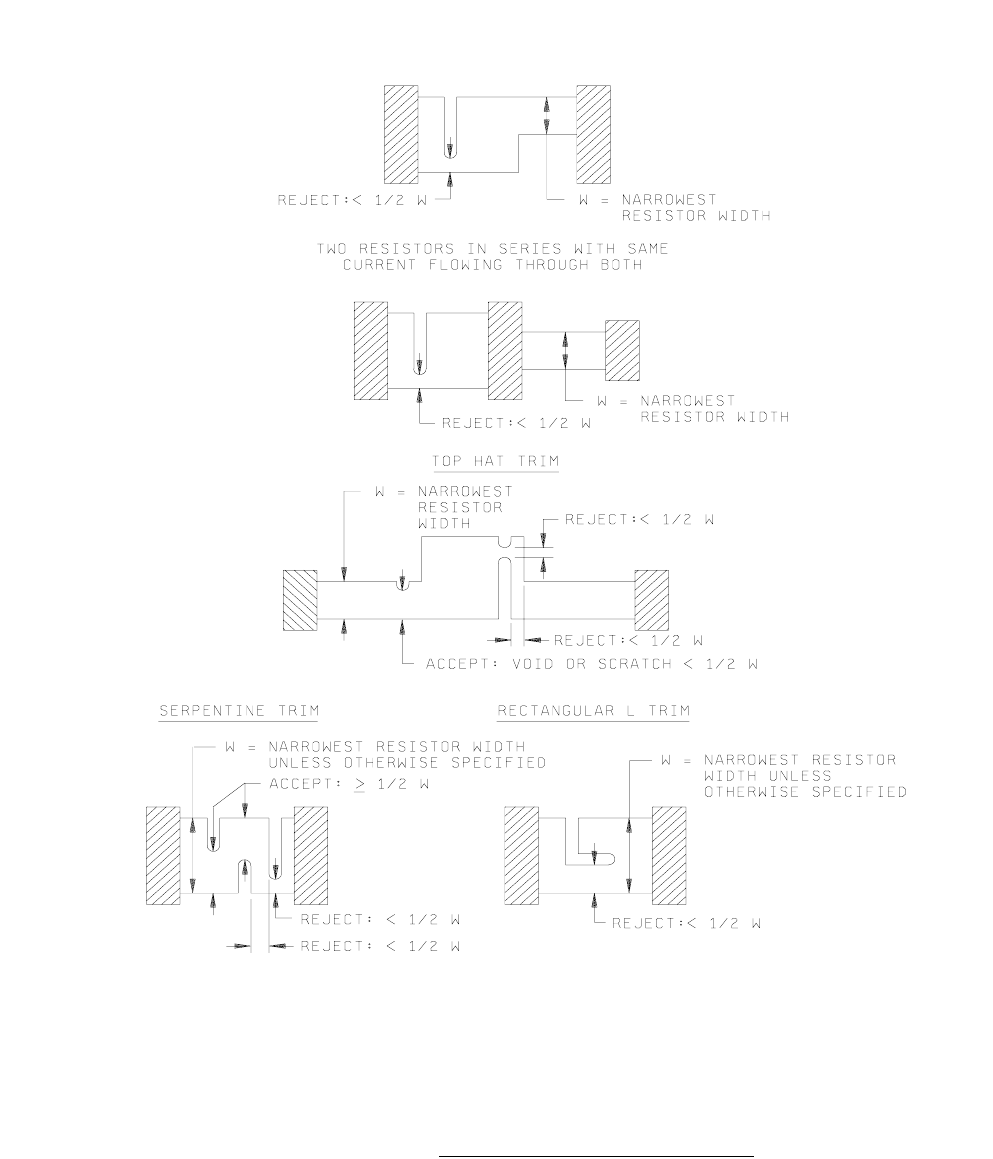
FIGURE 2010-31. Scratch, void and trim criteria for resistors
.
*
*
MIL-STD-883F
METHOD 2010.11
18 June 2004
34
Condition A Condition B
Class level S Class level B
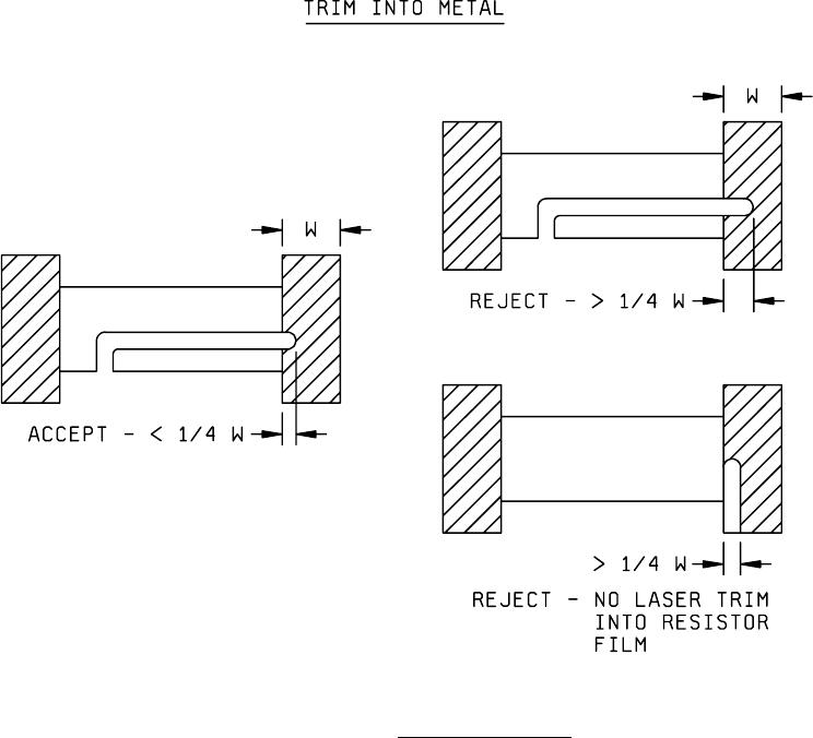
e. Trim path into the metallization except block resistors.
NOTE: This criteria can be excluded for trim paths into terminator ends of metallization runs. Conductors or resistors
may be trimmed open for link trims or by design.
f. Trim for block resistors which extends into the metallization (excluding bonding pads) more than 25 percent of the
original metal width (see figure 2010-32).
FIGURE 2010-32. Block resistor criteria
.
g. Pits into the silicon dioxide in the kerf which do not exhibit a line of separation between the pit and the resistor
material.
MIL-STD-883F
METHOD 2010.11
18 June 2004
35
Condition A Condition B
Class level S Class level B
3.2 Low power inspection
. Internal visual examination as required in 3.2.1 through 3.2.3 shall be conducted on each
microcircuit at low magnification range of 30X to 60X. In addition, the applicable criteria contained in 3.2.4 shall be
applicable where beam lead assembly technology is used and 3.2.5 shall be inspected at both high and low power as
indicated, high power magnification shall be same as 3.1, subject to conditions in 3b.
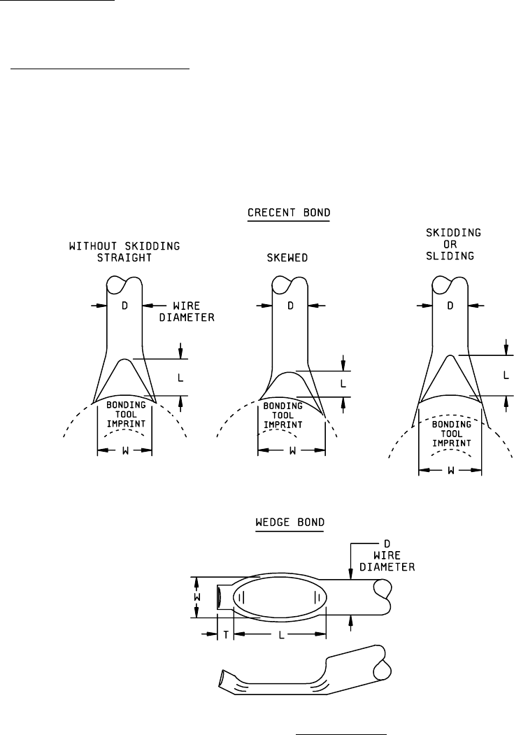
3.2.1 Lower power wire bond inspection
. This inspection and criteria shall be required inspection for the bond type (s)
and location(s) to which they are applicable when viewed from above (see figure 2010-33).
NOTE: The criteria applicable for bonds (called "wedgebonds" or "bonds") in this test method refers to the fully or partially
deformed area including the tool impression shown as "L and W" in figure. The criteria applicable for "bond tails" (or
"tails") in this test method refers to resulting length of bonding wire extending beyond the bond shown as "T" in
figure 2010-33. Tail is not part of bond.
FIGURE 2010-33. Bond dimensions
.