MIL- STD-883F 2004 TEST METHOD STANDARD MICROCIRCUITS.pdf - 第247页
MIL-STD-883F METHOD 2010.11 18 June 2004 37 Condition A Conditi on B Class le vel S Class lev el B 3.2.1. 4 General ( gold ball, wedge, and tai lles s) . As vi ewed from above, no device s hall be ac ceptabl e the exhibi…

MIL-STD-883F
METHOD 2010.11
18 June 2004
36
Condition A Condition B
Class level S Class level B
3.2.1.1 Gold ball bonds
. No devices shall be acceptable that exhibits:
a. Gold ball bonds on the die or package post wherein the ball bond diameter is less than 2.0 times or greater than
5.0 times the wire diameter.
b. Gold ball bonds where the wire exit is not completely within the periphery of the ball.
c. Gold ball bonds where the wire center exit is not within the boundaries of the unglassivated bonding pad area.
3.2.1.2 Wedge bonds
. No device shall be acceptable that exhibits:
a. Ultrasonic wedge bonds on the die or package post that are less than 1.2 times or more than 3.0 times the wire
diameter in width, or less than 1.5 times or more than 6.0 times the wire diameter in length.
b. Thermosonic wedge bonds on the die or package post that are less than 1.5 times or more than 3.0 times the wire
diameter in width or are less than 1.5 times or more than 6.0 times the wire diameter in length.
c. Bond width less than 1.0 times the wire diameter for aluminum wires 2.0 mils or greater in diameter.
d. Wedge bonds where the tool impression does not cover the entire width of the wire.
3.2.1.3 Tailless bonds (crescent, terminating capillary bond)
. No device shall be acceptable that exhibits:
a. Tailless bonds on the die or package post that are less than 1.2 times or more than 5.0 times the wire diameter in
width, or are less than 0.5 times or more than 3.0 times the wire diameter in length.
b. Tailless bonds where tool impression does not cover the entire width of the wire.

MIL-STD-883F
METHOD 2010.11
18 June 2004
37
Condition A Condition B
Class level S Class level B
3.2.1.4 General (gold ball, wedge, and tailless)
. As viewed from above, no device shall be acceptable the exhibits (see
figure 2010-16):
a. Bonds on the die where less than 75 percent of the a. Bonds on the die where less than 50 percent
bond is within the unglassivated bonding pad area. of the bond is within the unglassivated
bonding pad area.
b. Bond tails that do not exhibit a line of separation between the tail and unglassivated metallization, another wire,
wire bond, or wire bond tail, excluding common conductors and pads.
c. Bond tails extending over glassivated metallization where the glass exhibits evidence of crazing or cracking that
extends under the tail, excluding common conductors.
d. Wire bond tails: Tails that exceed 2 wire diameters in length on die or on post.
e. Bonds that are not completely within the boundaries of the package post. For glass sealed packages, bonds not
within 20 mils of the end of post.
f. Bonds (excluding bond tails) placed so that the f. Bonds (excluding bond tails) placed so that
horizontal distance between the bond and the horizontal distance between the bond and
glassivated or unglassivated noncommon metallization, glassivated or unglassivated noncommon
scribe lines, another bonding wire or bond is less metallization, scribe lines, another bonding
than .25 mils. wire or bond does not exhibit a visible line
of separation.
NOTE: When by design, there are multiple bonds on a common bonding pad or post they may not reduce the width of
an adjacent bond by more than 25 percent.
NOTE: For SOS devices, exclude the insulator scribe lines.
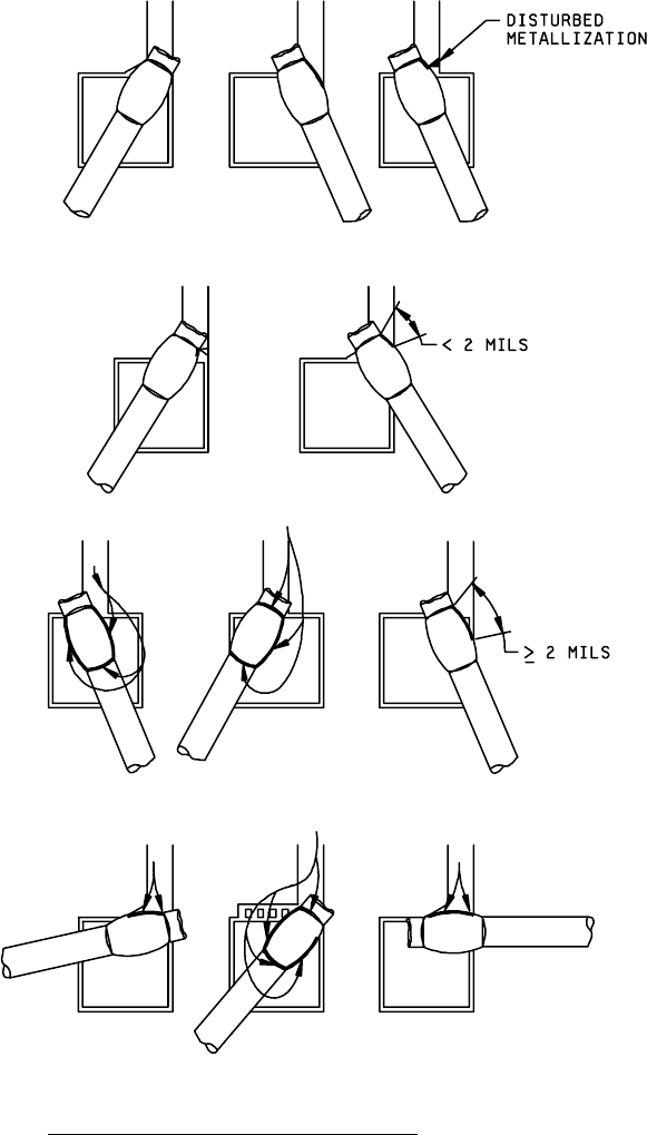
g. Bonds (excluding tails) placed such that less than 2.0 mils of bond periphery (on glassivated or unglassivated
areas) is exposed to an undisturbed die metallization connecting path to/from the entering/exiting metallization
stripe (see figure 2010-34).
NOTE 1: When bond tails prevent visibility of the connecting path and the metallization immediately adjacent to the
bond tail is disturbed, the device shall be unacceptable.
NOTE 2: When a fillet area exists, it is to be considered as part of the entering/exiting metallization stripe.
NOTE 3: This criteria is in addition to the bond placement criteria in 3.2.1.4a.
MIL-STD-883F
METHOD 2010.11
18 June 2004
38
Condition A Condition B
Class level S Class level B
Reject: Bond (excluding tails)
placed, such that less than 2.0
mils of bond periphery (on
glassivated or unglassivated
areas) is exposed by an
undisturbed die metallization
connecting path to/from the
entering/exiting metallization
stripe.
Reject: When bond tails prevent
visibility of the connecting path
to the bond periphery and the
metallization immediately adjacent
to the bond tail is disturbed.
Accept: Bonds (excluding tails)
placed, such that there is 2.0
mils or greater of bond periphery
(on glassivated or unglassivated
areas) exposed by an undisturbed
die metallization connecting path
to/from the entering/exiting
metallization stripe.
Arrows demonstrate the connecting
path to the bond periphery.
FIGURE 2010-34. Bonds at entering/exiting metallization stripe
.