MIL- STD-883F 2004 TEST METHOD STANDARD MICROCIRCUITS.pdf - 第252页
MIL-STD-883F METHOD 2010.11 18 June 2004 42 Condition A Conditi on B Class le vel S Class lev el B e. W ire( s) c ross ing wir e(s) when viewed fr om above, e. W ire( s) c ross ing wir e(s) when viewed fr om above, (excl…

MIL-STD-883F
METHOD 2010.11
18 June 2004
41
Condition A Condition B
Class level S Class level B
3.2.2 Internal wires
. During inspection for the requirements of 3.2.2, each device shall be viewed at any angle necessary
to determine full compliance to this specification, without damaging the device. No device shall be acceptable that exhibits:
a. Any wire with a separation of less than two wire a. Any wire with a separation of less than one
diameters to unglassivated operating metal,other wire diameter to unglassivated operating
bonds, another wire (common wiresexcluded),other metal, other bonds, another wire (common
package post, unglassivated die area (except for wires excluded), other package post,
wires or pads which are at the die or substrate unglassivated die area (except for wires or
potential), or any portion of the package pads which are at the die or substrate
including the plane of the lid to be attached. potential), or any conductive portion of the
package or the plane of the lid to be
attached.
NOTE: For condition A only. Within a 5.0 mil NOTE: For condition B only. Within a
radial distance from the perimeter of the bond 10.0 mil radial distance from the perimeter
on the die the separation shall be 1.0 mil of the bond on the die a line of separation
minimum. must be visible.
NOTE: For SOS devices, exclude the unglassivated insulator areas.
b. Nicks, bends, cuts, crimps, scoring, or neckdown in any wire that reduces the wire diameter by more than 25
percent.
c. Tearing at the junction of the wire and bond.
d. Any wire making a straight line run from a die bonding pad to a package post that has no arc.

MIL-STD-883F
METHOD 2010.11
18 June 2004
42
Condition A Condition B
Class level S Class level B
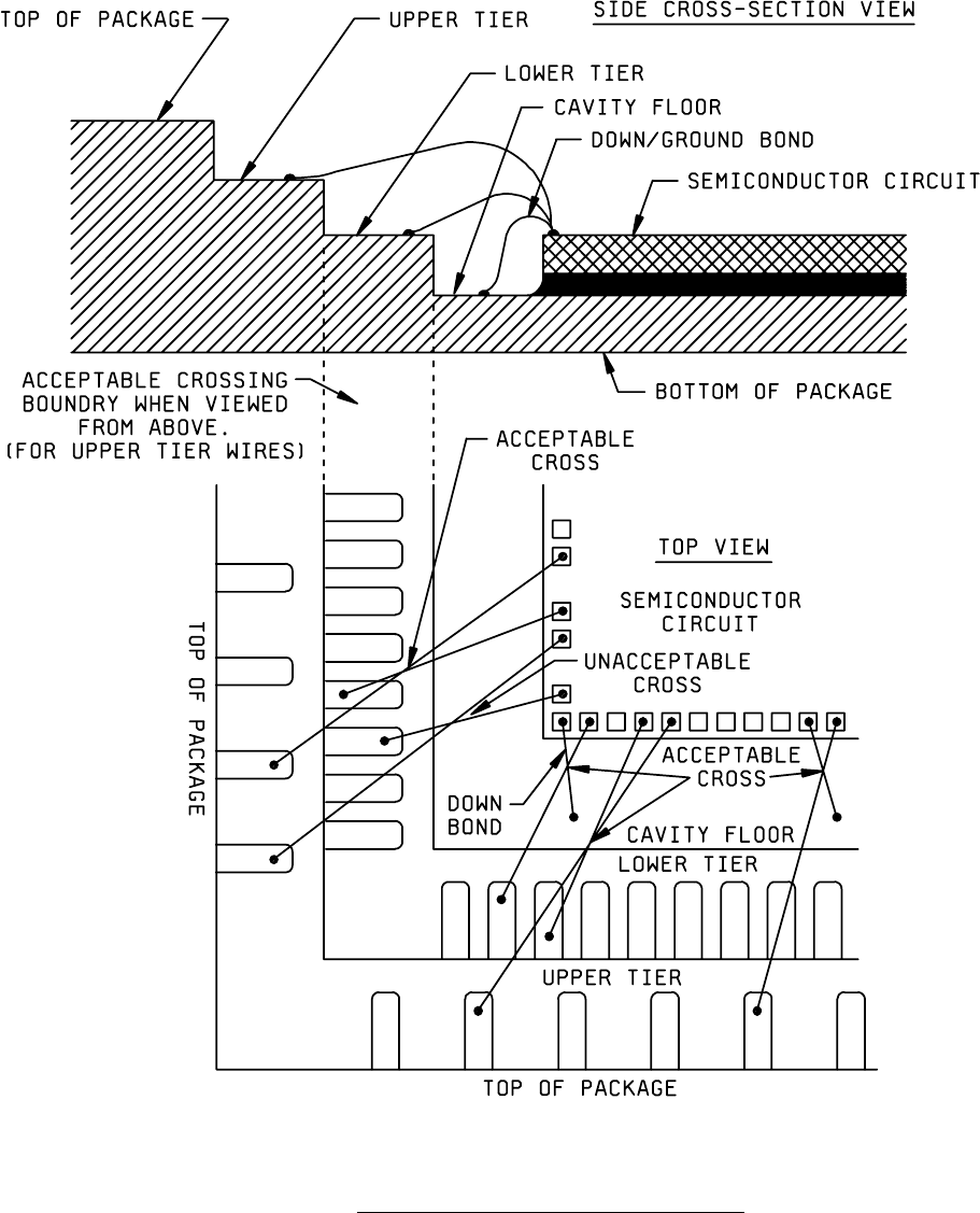
e. Wire(s) crossing wire(s) when viewed from above, e. Wire(s) crossing wire(s) when viewed from above,
(excluding common conductors) except in multitiered (excluding common conductors) except that wires
packages, where the crossing occurs within the crossing wires bonded to package posts that are
boundary of the lower wire bond tier(s) being crossed at difference heights, or wires bonded into the
or packages with down bond(s). In these situations, package cavity that cross are acceptable if they
the wires that cross are acceptable if they maintain maintain a minimum clearance of two wire diameters
a minimum clearance of two wire diameters (see figure (e.g., multitiered packages or packages with down
2010-35). bond chips).
NOTE: No bond wire shall cross more than one other
bond wire and there shall be no more than
4 crossovers or crossovers involving more than 10
percent of the total number of wires, whichever is
greater for any single package cavity.
f. Wire(s) not in accordance with bonding diagram.
3.2.3 Die mounting
.
3.2.3.1 Die mounting eutectic
. No device shall be acceptable that exhibits:
a. Die mounting material buildup that extends onto the top surface or extends vertically above the top surface of the
die.
b. Die mounting material (eutectic wetting) not visible around at least two complete sides or 75 percent of the die
perimeter, except for transparent die.
c. Transparent die with less than 50 percent of the area bonded.
d. Flaking of the die mounting material.
e. Balling or buildup of the die mounting material that does not exhibit a minimum of 50 percent peripheral fillet when
viewed from above or the accumulation of die mounting material is such that the height of the accumulation is
greater than the longest base dimension or the accumulation necks down at any point (see figure 2010-36).
MIL-STD-883F
METHOD 2010.11
18 June 2004
43
FIGURE 2010-35. Class level S criteria for wire(s) crossing wire(s)
.