MIL- STD-883F 2004 TEST METHOD STANDARD MICROCIRCUITS.pdf - 第255页
MIL-STD-883F METHOD 2010.11 18 June 2004 45 Condition A Conditi on B Class le vel S Class lev el B 3.2.3. 2 Die mounting noneut ecti c . No devic e shall be accept able that exhibits : a. Adhes ive mater ial i mmediatel …
MIL-STD-883F
METHOD 2010.11
18 June 2004
44
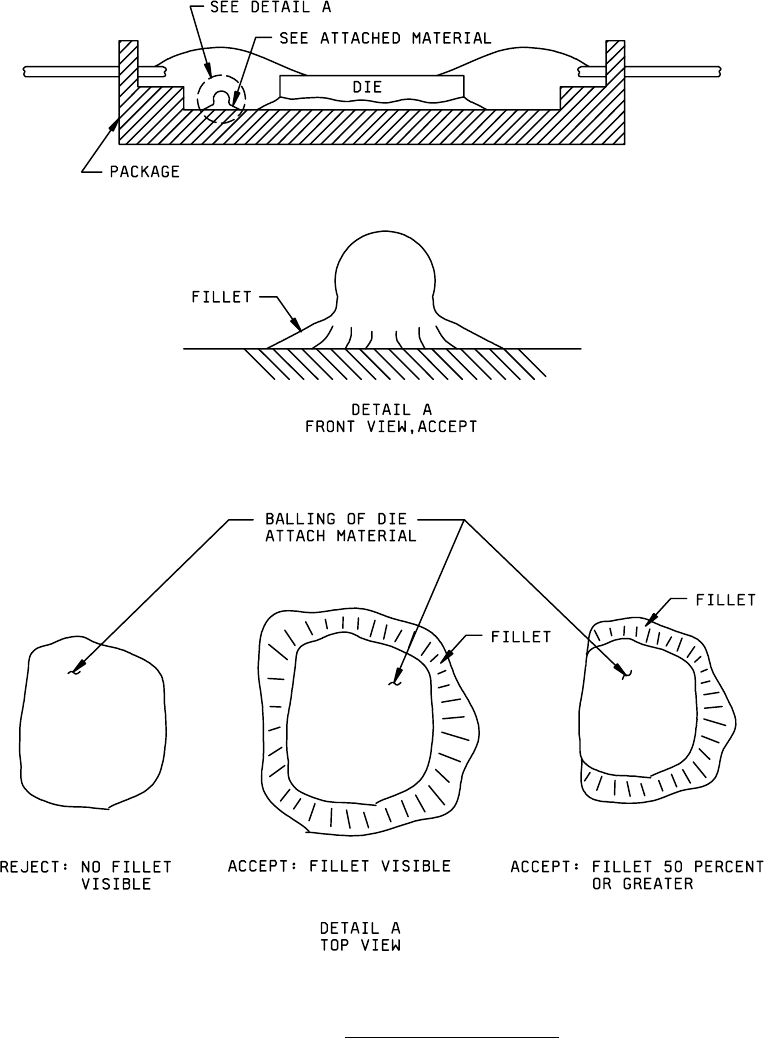
FIGURE 2010-36. Balling of die attach material
.

MIL-STD-883F
METHOD 2010.11
18 June 2004
45
Condition A Condition B
Class level S Class level B
3.2.3.2 Die mounting noneutectic
. No device shall be acceptable that exhibits:
a. Adhesive material immediately adjacent to the die that extends onto or vertically above the top surface of the die.
b. Adhesive fillet not visible along 75 percent of each side of the die.
c. Any flaking, peeling, or lifting of the adhesive material.
d. Separation, cracks, or fissures greater than or equal to 2 mils in width in the adhesive at the cavity wall or cavity
floor.
e. Crazing in the adhesive.
f. Adhesive material on the top surface of the die.
g. Adhesive that bridges package posts or is on the post bond area.
h. Any adhesive material that is connected to the fillet or conductive cavity (e.g. metal package base or metallized
floor of ceramic package), and extends up the cavity wall to within 1.0 mil of the package post.
i. Transparent die with less than 50 percent of the area bonded.
3.2.3.3 Die orientation
. No device shall be acceptable that exhibits:
a. Die not located or oriented in accordance with the applicable assembly drawing.
b. Die that appears to be obviously tilted (i.e., more than 10 degrees) with respect to the package cavity.
3.2.4 Beam lead construction
.
3.2.4.1 Bonds
. This inspection criteria shall apply to the completed bond area made, using either direct tool contact or a
compliant intermediate layer. No device shall be acceptable that exhibits:
a. Bonds where the tool impression does not completely cross the entire beam width.
b. Bonds on thin film substrate metal where the tool impression increases the beam lead width less than 15 percent
(10 percent for compliant bonds) or greater than 75 percent of the undeformed beam width.
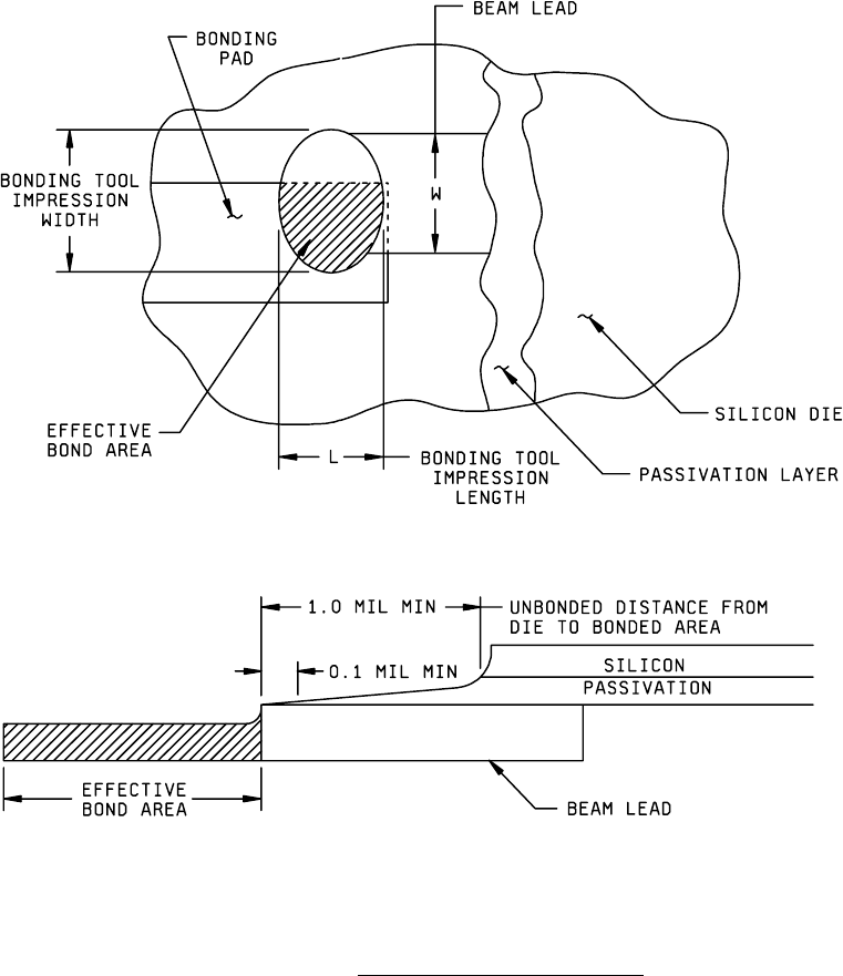
c. Bonds where the tool impression length is less than 1.0 mil (see figure 2010-37).
d. Bonding tool impression less than 1.0 mil from the die edge (see figure 2010-37).
MIL-STD-883F
METHOD 2010.11
18 June 2004
46
Condition A Condition B
Class level S Class level B
e. Effective bonded area less than 50 percent of that which would be possible for an exactly aligned beam (see
figure 2010-37).
FIGURE 2010-37. Beam lead bond area and location
.