MIL- STD-883F 2004 TEST METHOD STANDARD MICROCIRCUITS.pdf - 第264页
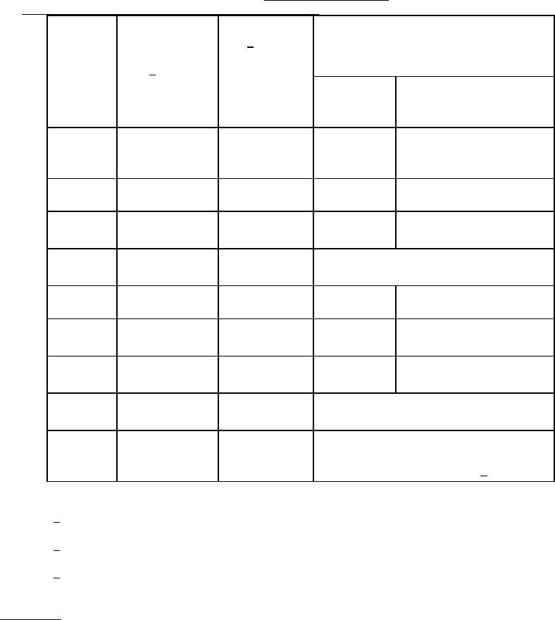
MIL-STD-883F METHOD 2011.7 22 March 1989 4 TABLE I. Mini mum bond str ength . Test condit ion W ire composi tion and diameter 1 / Constr ucti on 2 / Minimum bond s trength ( grams f orce) Pre seal Post s eal and any othe…
MIL-STD-883F
METHOD 2011.7
22 March 1989
3
b. For external bonds connecting device to wiring board or substrate:
(b-1) Lead or terminal break at deformation point (weld affected region).
(b-2) Lead or terminal break at point not affected by bonding process.
(b-3) Failure in bond interface (in solder or at point of weld interface between lead or terminal and the board or
substrate conductor to which the bond was made).
(b-4) Conductor lifted from board or substrate.
(b-5) Fracture within board or substrate.
c. For flip-chip configurations:
(c-1) Failure in the bond material or pedestal, if applicable.
(c-2) Fracture of die (or carrier) or substrate (removal of portion of die or substrate immediately under the bond).
(c-3) Lifted metallization (separation of metallization or bonding pedestal from die (or carrier) or substrate.
d. For beam lead devices:
(d-1) Silicon broken.
(d-2) Beam lifting on silicon.
(d-3) Beam broken at bond.
(d-4) Beam broken at edge of silicon.
(d-5) Beam broken between bond and edge of silicon.
(d-6) Bond lifted.
(d-7) Lifted metallization (separation of metallization) from die, separation of bonding pad.
(d-8) Lifted metallization.
NOTE: RF/microwave hybrids that require extremely flat loops which may cause erroneous wire pull data may use the
following formula to determine the proper wire pull value.
V
1
= V
2
sin Θ
Where: V
1
= New value to pull test.
V
2
= Table I value for size wire tested.
Θ = Greatest calculated wire loop angle (figure 2011-2).
Also, RF/microwave hybrids that contain wires that cannot be accessed with a pull hook must be duplicated on a test
coupon in such a way to allow hook access for purposes of pull testing. These wires are to be bonded at the same time
the production hybrids are bonded using the same setup, operator, and schedule. The test coupon wires are to be pull
tested in lieu of the tuning or inaccessible wires on the production hybrid. Failures on the test coupon shall be
considered as failures to production units and appropriate action is to be taken in accordance with the applicable
specification (figure 2011-3).
MIL-STD-883F
METHOD 2011.7
22 March 1989
4
TABLE I. Minimum bond strength.
Test
condition
Wire
composition
and diameter
1
/
Construction
2
/
Minimum bond strength (grams force)
Pre seal Post seal and any other
processing and screening
when applicable
A --- --- Given in
applicable
document
Given in applicable
document
C or D AL 0.0007 in
AU 0.0007 in
Wire 1.5
2.0
1.0
1.5
C or D AL 0.0010 in
AU 0.0010 in
Wire 2.5
3.0
1.5
2.5
C or D AL 0.00125 in
AU 0.00125 in
Wire Same bond strength limits
as the 0.0013 in wire
C or D AL 0.0013 in
AU 0.0013 in
Wire 3.0
4.0
2.0
3.0
C or D AL 0.0015 in
AU 0.0015 in
Wire 4.0
5.0
2.5
4.0
C or D AL 0.0030 in
AU 0.0030 in
Wire 12.0
15.0
8.0
12.0
F Any Flip-clip 5 grams-force x
number of bonds (bumps)
G or H Any Beam lead 30 grams force in accordance with
linear millimeter of nominal undeformed
(before bonding) beam width. 3
/
1
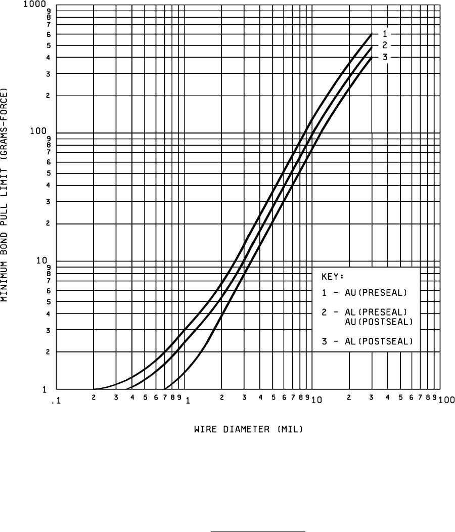
/ For wire diameters not specified, use the curve of figure 2011-1 to determine the bond
pull limit.
2
/ For ribbon wire, use the equivalent round wire diameter which gives the same
cross-sectional area as the ribbon wire being tested.
3
/ For condition G or H, the bond strength shall be determined by dividing the breaking
force by the total of the nominal beam widths before bonding.
4. SUMMARY
. The following details shall be specified in the applicable acquisition document:
a. Test condition letter (see 3).
b. Minimum bond strength if other than specified in 3.2 or details of required strength distributions if applicable.
c. Sample size number and accept number or number and selection of bond pulls to be tested on each device, and
number of devices, if other than 4.
d. For test condition A, angle of bond peel if other than 90°, and bond strength limit (see 3.2).
e. Requirement for reporting of separation forces and failure categories, when applicable (see 3.2.1).
MIL-STD-883F
METHOD 2011.7
22 March 1989
5
NOTE: The minimum bond strength should be taken from table I. Figure 2011-1
may be used for wire diameters not specified in table I.
FIGURE 2011-1. Minimum bond pull limits
.