MIL- STD-883F 2004 TEST METHOD STANDARD MICROCIRCUITS.pdf - 第267页
MIL-STD-883F METHOD 2012.7 1 June 1993 1 METHOD 2012.7 RADIOGRAPHY 1. Purpos e . The purpos e of thi s examination i s to nondes truc tivel y detect defect s wit hin the s ealed cas e, espec iall y those r esult ing fr o…
MIL-STD-883F
METHOD 2011.7
22 March 1989
6
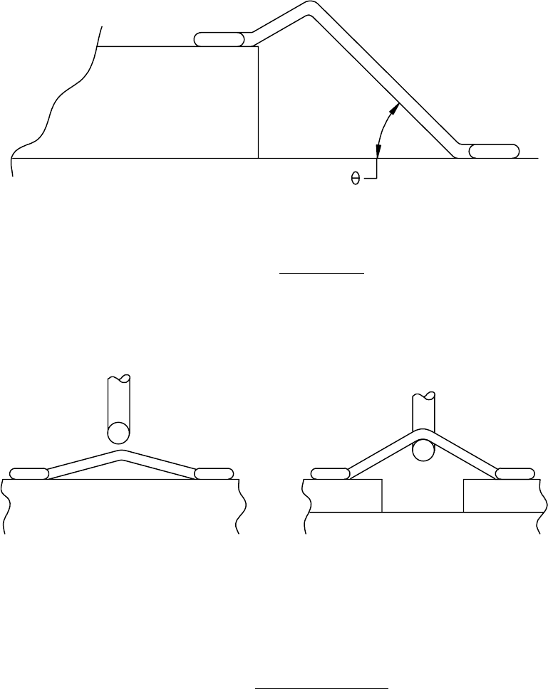
FIGURE 2011-2. Wire loop angle
.
FIGURE 2011-3. Flat loop wire pull testing
.

MIL-STD-883F
METHOD 2012.7
1 June 1993
1
METHOD 2012.7
RADIOGRAPHY
1. Purpose
. The purpose of this examination is to nondestructively detect defects within the sealed case, especially
those resulting from the sealing process and internal defects such as foreign objects, improper interconnecting wires,
and voids in the die attach material or in the glass when glass seals are used. It establishes methods, criteria, and
standards for radiographic examination of semiconductor and hybrid devices.
NOTE: For certain device types, opacity of the construction materials (packages or internal attachment) may
effectively prevent radiographic identification of certain types of defects from some or all possible viewing angles. This
factor should be considered in relation to the design of each device when application of this test method is specified.
2. Apparatus
. The apparatus and material for this test shall include:
a. Radiographic equipment with a sufficient voltage range to penetrate the device. The focal distance shall be
adequate to maintain a sharply defined image of an object with a major dimension of 0.0254 mm (0.001 inch).
b. Radiographic film: Very fine grain industrial X-ray film grade, either single or double emulsion.
c. Radiographic viewer: Capable of 0.0254 mm (0.001 inch) resolution in major dimension.
d. Holding fixtures: Capable of holding devices in the required positions without interfering with the accuracy or ease
of image interpretation.
e. Radiographic quality standards: Capable of verifying the ability to detect all specified defects.
f. Film holder: A 1.6 mm (0.0625 inch) minimum lead-topped table or lead-backed film holders to prevent back
scatter of radiation.
3. Procedure
. The X-ray exposure factors, voltage, milliampere and time settings shall be selected or adjusted as
necessary to obtain satisfactory exposures and achieve maximum image details within the sensitivity requirements for
the device or defect features the radiographic test is directed toward. The X-ray voltage shall be the lowest consistent
with these requirements and shall not exceed 200 kV.
3.1 Mounting and views
. The devices shall be mounted in the holding fixture so that the devices are not damaged or
contaminated and are in the proper plane as specified. The devices may be mounted in any type of fixture and masking
with lead diaphragms or barium clay may be employed to isolate multiple specimens provided the fixtures or masking
material do not block the view from X-ray source to the film of any portion of the body of the device.
3.1.1 Views
.
3.1.1.1 Flat packages, dual-in-line packages, hybrid packages, and single ended cylindrical devices
. Flat packages,
dual-in-line packages, hybrid packages, and single ended cylindrical devices, unless otherwise specified, shall have one
view taken with the X-rays penetrating in the Y direction as defined on figures 1 and 2 of MIL-STD-883, GENERAL
REQUIREMENTS. When more than one view is required, the second and third views, as applicable, shall be taken with
the X-rays penetrating in the Z and X direction respectively (either Z or X for flat packages). The die/cavity interface
shall be positioned as close as possible to the film to avoid distortion.

MIL-STD-883F
METHOD 2012.7
1 June 1993
2
3.1.1.2 Stud-mounted and cylindrical axial lead devices. Stud-mounted and cylindrical axial lead devices, unless
otherwise specified, shall have one view taken with the X-rays penetrating in the X direction as defined on figures 1 and
2 of MIL-STD-883, GENERAL REQUIREMENTS. When more than one view is required, the second and third views, as
applicable, shall be taken with the X-rays penetrating in the Z direction and at 45° between the X and Z direction. The
die/cavity interface shall be positioned as close as possible to the film to avoid distortion.
3.2 Radiographic quality standard
. Each radiograph shall have at least two quality standards exposed with each view,
located (and properly identified) in opposite corners of the film. These penetrameters shall be of a radiographic density
nearest the density of the devices being inspected. The radiographic quality standard shall consist of a suitable ASTM
penetrameter as described in the DOD adopted standard ASTM E 801 Standard Practice for Controlling Quality of
Radiographic Testing of Electronic Devices, or equivalent.
3.3 Film and marking
. The radiographic film shall be in a film holder backed with a minimum of 1/16 inch lead or the
holder shall be placed on the lead topped table. The film shall be identified using techniques that print the following
information, photographically, on the radiograph:
a. Device manufacturer's name or code identification number.
b. Device type or Part or Identifying Number.
c. Production lot number or date code or inspection lot number.
d. Radiographic film view number and date.
e. Device serial or cross reference numbers, when applicable.
f. X-ray laboratory identification, if other than device manufacturer.
3.3.1 Nonfilm techniques, when specified
. The use of nonfilm techniques is permitted if the equipment is capable of
producing results of equal quality when compared with film techniques, and all requirements of this method are complied
with, except those pertaining to the actual film. Radiographic quality standards, as specified in 3.2, may be used at the
beginning and end of each inspection lot if equipment settings are not modified.
3.3.2 Serialized devices
. When device serialization is required, each device shall be readily identified by a serial
number. They shall be radiographed in consecutive, increasing serial order. When a device is missing, the blank space
shall contain either the serial number or other X-ray opaque object to readily identify and correlate X-ray data. When
large skips occur within serialized devices, the serial number of the last device before the skip and the first device after
the skip may be used in place of the multiple opaque objects.
3.3.3 Special device marking
. When specified (see 4.c), the devices that have been X-rayed and found acceptable
shall be identified with a blue dot on the external case. The blue dot shall be approximately 1.6 mm (0.0625 inch) in
diameter. The color selected from FED-STD-595 shall be any shade between 15102-15123 or 25102-25109. The dot
shall be placed so that it is readily visible but shall not obliterate other device marking.
3.4 Tests
. The X-ray exposure factor shall be selected to achieve resolution of 0.0254 mm (0.001 inch) major
dimension, less than 10 percent distortion and an "H" and "D" film density between 1 and 2.5 in the area of interest of the
device image. Radiographs shall be made for each view required (see 4).
3.5 Processing
. The radiographic film manufacturer's recommended procedure shall be used to develop the exposed
film, and film shall be processed so that it is free of processing defects such as fingerprints, scratches, fogging, chemical
spots, blemishes, etc.