MIL- STD-883F 2004 TEST METHOD STANDARD MICROCIRCUITS.pdf - 第29页
MIL-STD-883F METHOD 1003 1 May 1968 1 METHOD 1003 INSULATION RESISTANCE 1. PURPOSE . This test is t o measure t he resi stanc e offer ed by the ins ulating member s of a c omponent part to an impres sed di rect voltage t…
MIL-STD-883F
METHOD 1002
1 May 1968
2
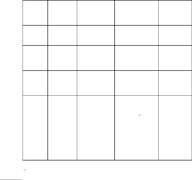
Test
condition
Number of
cycles
Duration of
each immersion
(minutes)
Immersion bath
(cold)
Temperature
of cold bath
°C
A
2
15
Fresh (tap) water
25 +10
-5
B
2
15
Saturated solution
of sodium chloride
and water
25 +10
-5
C
5
60
Saturated solution
of sodium chloride
and water
0 ±3
D
5
60
(Parts by volume)
Water -48 parts
Methanol 1
/ -50
parts
Morpholine -1
part
3.5-dimethyl-1-
hexyn-3-o1-1 part
Stannous
chloride -
5 grams
0 ±3
1
/ Synonyms are tetrahydro-1, 4-oxazine and diethylenimide oxide.
4. SUMMARY
. The following details must be specified in the applicable acquisition document:
a. Test condition letter (see 3). Unless otherwise specified, condition C shall be used.
b. Time after final cycle allowed for measurements, if other than that specified (see 3).
c. Measurements after final cycle (see 3). Unless otherwise specified, measurements shall include pin-to-pin
resistance, pin-to-case resistance and full electrical test of all device characteristics or parameters listed in the
applicable acquisition document. Final evaluation shall include external visual examination for legibility of device
markings and for evidence of discoloration or corrosion of package and leads.
d. Dissection and internal examination, where applicable (see 3).
MIL-STD-883F
METHOD 1003
1 May 1968
1
METHOD 1003
INSULATION RESISTANCE
1. PURPOSE
. This test is to measure the resistance offered by the insulating members of a component part to an
impressed direct voltage tending to produce a leakage of current through or on the surface of these members. Insulation-
resistance measurements should not be considered the equivalent of dielectric withstanding voltage or electric breakdown
tests. A clean, dry insulation may have a high insulation resistance, and yet possess a mechanical fault that would cause
failure in the dielectric withstanding voltage test. Since insulating members composed of different materials or combinations
of materials may have inherently different insulation resistances, the numerical value of measured insulation resistance
cannot properly be taken as a direct measure of the degree of cleanliness or absence of deterioration.
1.1 Factors affecting use
. Factors affecting insulation-resistance measurements include temperature, humidity, residual
charges, charging currents or time constant of instrument and measured circuit, test voltage, previous conditioning, and
duration of uninterrupted test voltage application (electrification time). In connection with this last-named factor, it is
characteristic of certain components (for example, capacitors and cables) for the current to usually fall from an
instantaneous high value to a steady lower value at a rate of decay which depends on such factors as test voltage,
temperature, insulating materials, capacitance, and external circuit resistance. Consequently, the measured insulation
resistance will increase for an appreciable time as test voltage is applied uninterruptedly. Because of this phenomenon, it
may take many minutes to approach maximum insulation-resistance readings, but specifications usually require that
readings be made after a specified time. This shortens the testing time considerably while still permitting significant test
results, provided the insulation resistance is reasonably close to steady-state value, the current versus time curve is known,
or suitable correction factors are applied to these measurements. For certain components, a steady instrument reading may
be obtained in a matter of seconds. When insulation-resistance measurements are made before and after a test, both
measurements should be made under the same conditions.
2. APPARATUS
. Insulation-resistance measurements shall be made on an apparatus suitable for the characteristics of
the component to be measured such as a megohm bridge, megohmmeter, insulation-resistance test set, or other suitable
apparatus.
3. PROCEDURE. When special preparations or conditions such as special test fixtures, reconnections, grounding,
isolation, low atmospheric pressure, humidity, or immersion in water are required, they shall be specified. Insulation-
resistance measurements shall be made between the mutually insulated points or between insulated points and
ground, as specified. When electrification time is a factor, the insulation-resistance measurements shall be made
immediately after the specified time (see 4) of uninterrupted test voltage application, unless otherwise specified.
However, if the instrument-reading indicates that an insulation resistance meets the specified limit, and is steady or
increasing, the test may be terminated before the end of the specified period. When more than one measurement is
specified, subsequent measurements of insulation resistance shall be made using the same polarity as the initial
measurements. Unless otherwise specified, the direct potential applied to the specimen shall be that indicated by
one of the test condition letters, as specified below, and insulation resistance measurements shall be made with both
polarities of the applied voltage:
Test condition
Test potential
A 10 volts ±10%
B 25 volts ±10%
C 50 volts ±10%
D 100 volts ±10%
E 500 volts ±10%
F 1,000 volts ±10%
For inplant quality conformance testing, any voltage may be used provided it is equal to or greater than the minimum
potential allowed by the applicable test condition. Unless otherwise specified, the measurement error at the
insulation-resistance value shall not exceed 10 percent. Proper guarding techniques shall be used to prevent erroneous
readings due to leakage along undesired paths.

MIL-STD-883F
METHOD 1003
1 May 1968
2
4. SUMMARY
. The following details must be specified in the applicable acquisition document:
a. Test condition letter, or other test potential, if specified (see 3).
b. Special preparations or conditions, if required (see 3).
c. Points of measurement (see 3). Unless otherwise specified, insulation resistance shall be measured between the
device leads (all leads electrically connected to each other or to a common point) and the device case, and the
measured resistance shall be no less than 15 megohms.
d. Electrification time, if critical (see 1.1).
e. Insulation resistance in terms of maximum leakage current at a specified test voltage. Unless otherwise specified,
the maximum leakage between any adjacent disconnected leads shall not exceed 100 nanoampere at 100 volts
dc.