MIL- STD-883F 2004 TEST METHOD STANDARD MICROCIRCUITS.pdf - 第304页
MIL-STD-883F METHOD 2017.8 18 June 2004 14 Class H Class K f. Bonding t ool impr ess ion les s than 1. 0 mil fr om the die edge ( see Figur e 2017-6). g. Effec tive bonded ar ea less than 50 perc ent of t hat whic h woul…
MIL-STD-883F
METHOD 2017.8
18 June 2004
13
Class H Class K
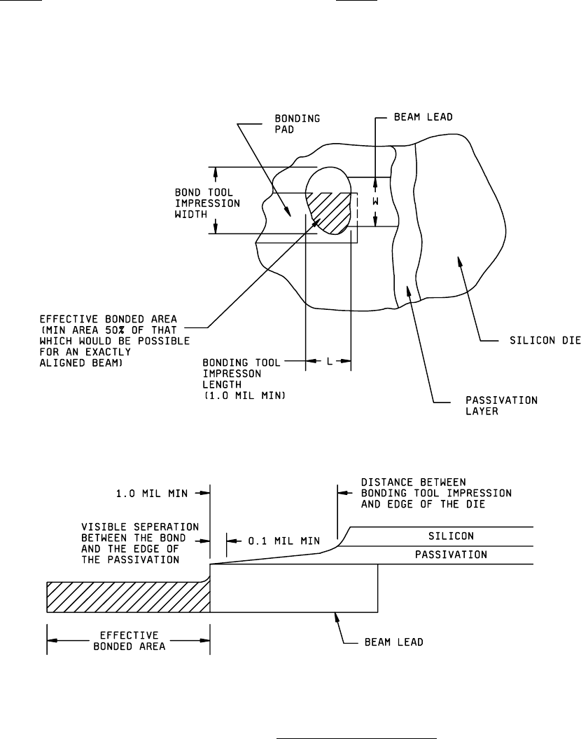
e. Bonds where the tool impression length is less than 1.0 mil (see Figure 2017-6)
FIGURE 2017-6. Beam Lead Area and Location
.
MIL-STD-883F
METHOD 2017.8
18 June 2004
14
Class H Class K
f. Bonding tool impression less than 1.0 mil from the die edge (see Figure 2017-6).
g. Effective bonded area less than 50 percent of that which would be possible for an exactly aligned beam (see
Figure 2017-6).
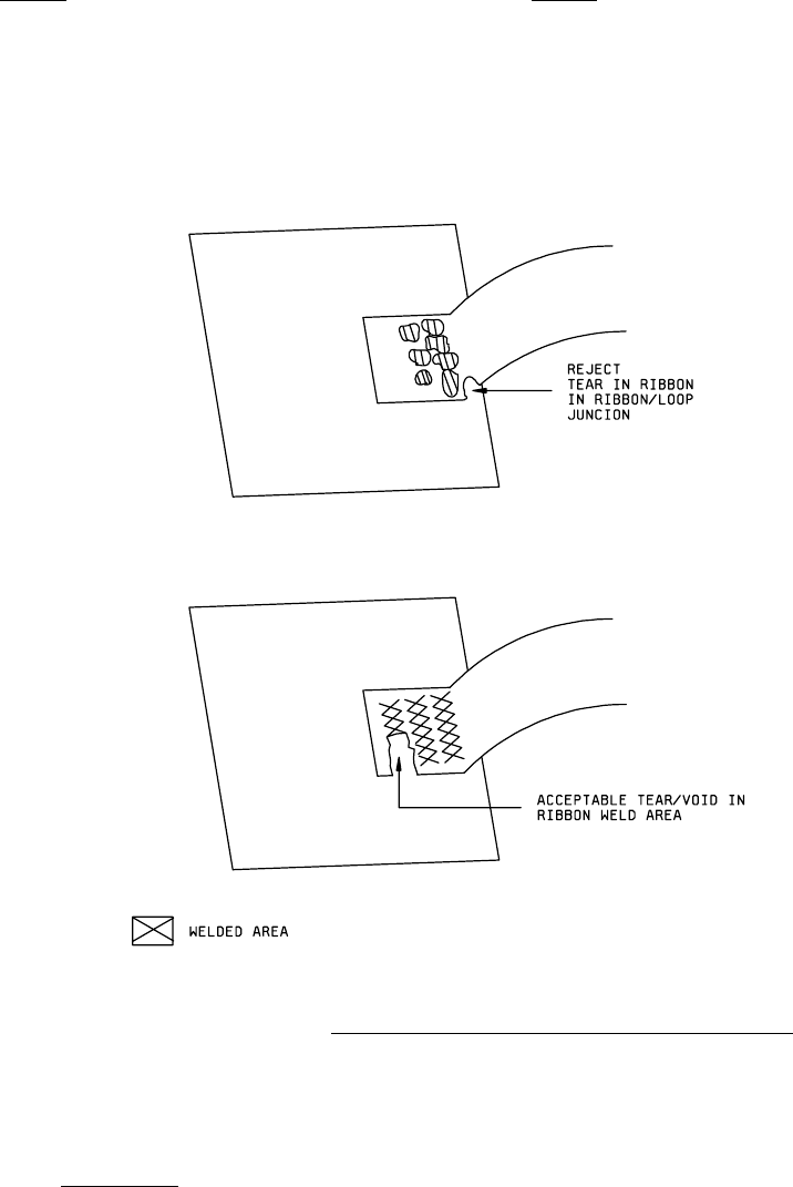
h. Any tears in the beam lead between the bond junction nearest the die body and the die or in the bonded area of
the beam lead within a distance equal to 50 percent the beam lead width (see Figure 2017-7).
FIGURE 2017-7. Acceptable/rejectable tears or voids in ribbon weld area
.
i. An absence of visible separation between the bond and the edge of the passivation layer (see Figure 2017-6).
j. An absence of visible separation between a beam lead and non-electrically common metallization. This criteria applies
for both glassivated and unglassivated metallization.
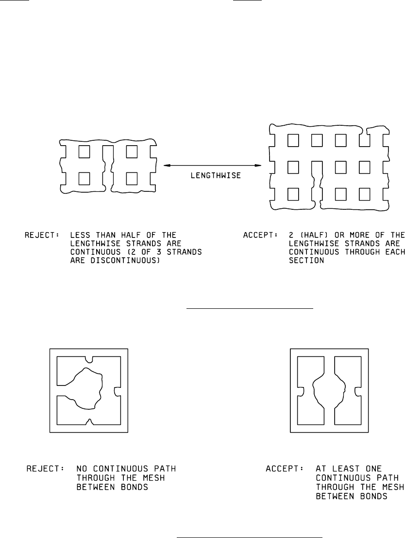
3.1.5.6 Mesh bonding
. No device shall be acceptable that exhibits the following:
a. Less than 50 percent of the bond is on substrate metallization.
MIL-STD-883F
METHOD 2017.8
18 June 2004
15
Class H Class K
b. The number of continuous strands along the mesh is less than 50 percent of lengthwise strands through each
section. (see Figure 2017-8a).
c. Less than one continuous Less than two continuous conducting
conducting path(s) through a path(s) through a bond (see Figure
bond (see Figure 2017-8b). 2017-8b).
FIGURE 2017-8a. Criteria for strands along the mesh
.
FIGURE 2017-8b. Criteria for continuous conducting paths
.