MIL- STD-883F 2004 TEST METHOD STANDARD MICROCIRCUITS.pdf - 第324页
MIL-STD-883F METHOD 2018.4 18 June 2004 12 NOTE S: 1. 1, 2, 3, and 4 are di rect ional edges . 2. 1 is a major cur rent c arryi ng edge. FIGURE 2018-2. Direct ional edge .
MIL-STD-883F
METHOD 2018.4
18 June 2004
11
A
NOTES:
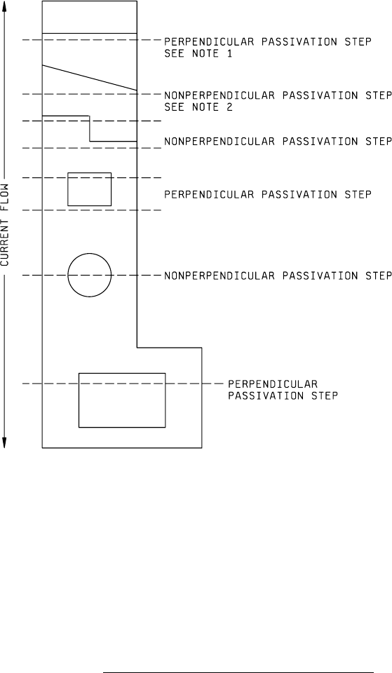
1. Cross-sectional planes are denoted by dashed lines.
2. All passivation steps nonperpendicular to current flow must be projected onto cross-sectional planes
perpendicular to current flow for purpose of cross-sectional area calculations.
3. The purpose of this cross-sectional plane illustration is two-fold:
To provide a consistent and convenient means to facilitate the calculation of the
appropriate cross-sectional area.
To insure that the cross-sectional area of the metallization in a major current
carrying direction is reduced to no more than 50 percent (30 percent when appropriate)
for the topographical variation under consideration.
FIGURE 2018-1. Cross-sectional planes at various passivation steps
.
MIL-STD-883F
METHOD 2018.4
18 June 2004
12
NOTES:
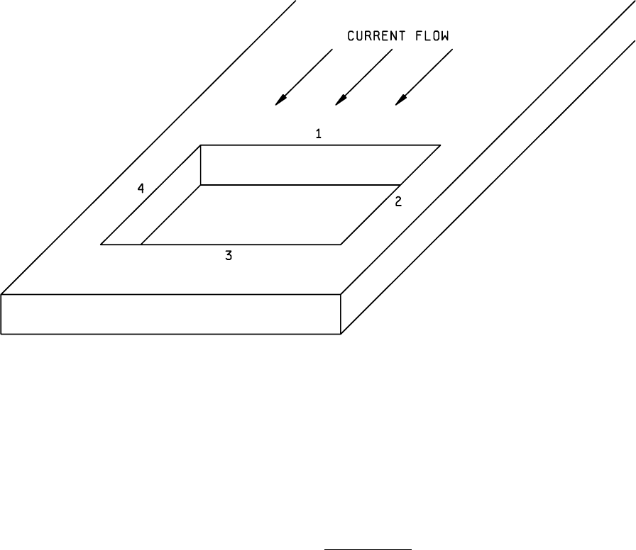
1. 1, 2, 3, and 4 are directional edges.
2. 1 is a major current carrying edge.
FIGURE 2018-2. Directional edge
.
MIL-STD-883F
METHOD 2018.4
18 June 2004
13
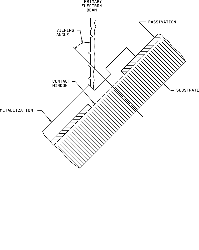
FIGURE 2018-3. Viewing angle
.