MIL- STD-883F 2004 TEST METHOD STANDARD MICROCIRCUITS.pdf - 第34页
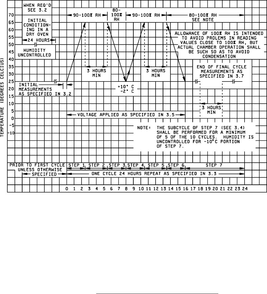
MIL-STD-883F METHOD 1004.7 17 August 1987 4 FIGURE 1004-1. Graphic al repres entati on of mois ture- resi stanc e test .

MIL-STD-883F
METHOD 1004.7
17 August 1987
3
4. SUMMARY
. The following details shall be specified in the applicable acquisition document:
a. Initial measurements and conditions, if other than room ambient (see 3.1 and 3.2).
b. Applied voltage, when applicable (see 3.5), and bias configuration, when required. This bias configuration shall
be chosen in accordance with the following guidelines:
(1) Only one supply voltage (V) either positive or negative is required, and an electrical ground (GND) or
common terminal. The magnitude of V will be the maximum such that the specified absolute maximum
ratings are not exceeded and test conditions are optimized.
(2) All normally specified voltage terminals and ground leads shall be connected to GND, unless otherwise
specified.
(3) All data inputs, unless otherwise specified, shall be connected to V. The polarity and magnitude of V is
chosen to minimize internal power dissipation and current flow into the device. All extender inputs shall be
connected to GND, unless otherwise specified.
(4) All additional leads, e.g., clock, set, reset, outputs, etc., considered individually, shall be connected to V or
GND whichever minimizes current flow.
(5) Leads with no internal connection shall be biased to V or GND whichever is opposite to an adjacent lead.
c. Final measurements (see 3.7). Final measurements shall include all electrical characteristics and parameters
which are specified as end-point electrical parameters.
d. Number of cycles, if other than 10 (see 3.3).
e. Conditioning in dry oven before initial measurements, if required (see 3.2).
MIL-STD-883F
METHOD 1004.7
17 August 1987
4
FIGURE 1004-1. Graphical representation of moisture-resistance test
.

MIL-STD-883F
METHOD 1005.8
1 June 1993
1
METHOD 1005.8
STEADY-STATE LIFE
1. PURPOSE
. The steady-state life test is performed for the purpose of demonstrating the quality or reliability of devices
subjected to the specified conditions over an extended time period. Life tests conducted within rated operating conditions
should be conducted for a sufficiently long test period to assure that results are not characteristic of early failures or "infant
mortality," and periodic observations of results should be made prior to the end of the life test to provide an indication of any
significant variation of failure rate with time. Valid results at shorter intervals or at lower stresses require accelerated test
conditions or a sufficiently large sample size to provide a reasonable probability of detection of failures in the sample
corresponding to the distribution of potential failures in the lot(s) from which the sample was drawn. The test conditions
provided in 3 below are intended to reflect these considerations.
When this test is employed for the purpose of assessing the general capability of a device or for device qualification tests in
support of future device applications requiring high reliability, the test conditions should be selected so as to represent the
maximum operating or testing (see test condition F) ratings of the device in terms of electrical input(s), load and bias and the
corresponding maximum operating or testing temperature or other specified environment.
2. APPARATUS
. Suitable sockets or other mounting means shall be provided to make firm electrical contact to the
terminals of devices under test in the specified circuit configuration. Except as authorized by the acquiring or qualifying
activity, the mounting means shall be so designated that they will not remove internally-dissipated heat from the device by
conduction, other than that removed through the device terminals, the necessary electrical contacts and the gas or liquid
chamber medium. The apparatus shall provide for maintaining the specified biases at the terminals of the device under test
and, when specified, monitoring of the input excitation or output response. Power supplies and current-setting resistors shall
be capable of maintaining the specified operating conditions as minimal throughout the testing period, despite normal
variations in source voltages, ambient temperatures, etc. When test conditions result in significant power dissipation, the
test apparatus shall be arranged so as to result in the approximate average power dissipation for each device whether
devices are tested individually or in a group. The test circuits need not compensate for normal variations in individual device
characteristics, but shall be so arranged that the existence of failed or abnormal (i.e., open, short, etc.) devices in a group
does not negate the effect of the test for other devices in the group.
3. PROCEDURE
. The microelectronic devices shall be subjected to the specified test condition (see 3.5) for the
specified duration at the specified test temperature, and the required measurements shall be made at the specified
intermediate points and end points. QML manufactures who are certified and qualified to MIL-PRF-38535 may modify the
time or the condition independently from the regression conditions contained in table I or the test condition/circuit specified
in the device specification or standard microcircuit drawing provided the modification is contained in the manufacturer's QM
plan and the "Q" certification identifier is marked on the devices. Lead-, stud-, or case-mounted devices shall be mounted
by the leads, stud, or case in their normal mounting configuration, and the point of connection shall be maintained at a
temperature not less than the specified ambient temperature. The test condition, duration, sample size, and temperature
selected prior to test shall be recorded and shall govern for the entire test. Test boards shall not employ load resistors
which are common to more than one device, or to more than one output pin on the same device.
3.1 Test duration
.
3.1.1 Test duration - standard life
. The life test duration shall be 1,000 hours minimum at 125°C , unless otherwise
specified or allowed (see 3.2.1). After the specified duration of the test, the device shall be removed from the test conditions
and allowed to reach standard test conditions. Where the purpose of this test is to demonstrate compliance with a specified
lambda (8), the test may be terminated at the specified duration or at the point of rejection if this occurs prior to the specified
test duration.