MIL- STD-883F 2004 TEST METHOD STANDARD MICROCIRCUITS.pdf - 第347页
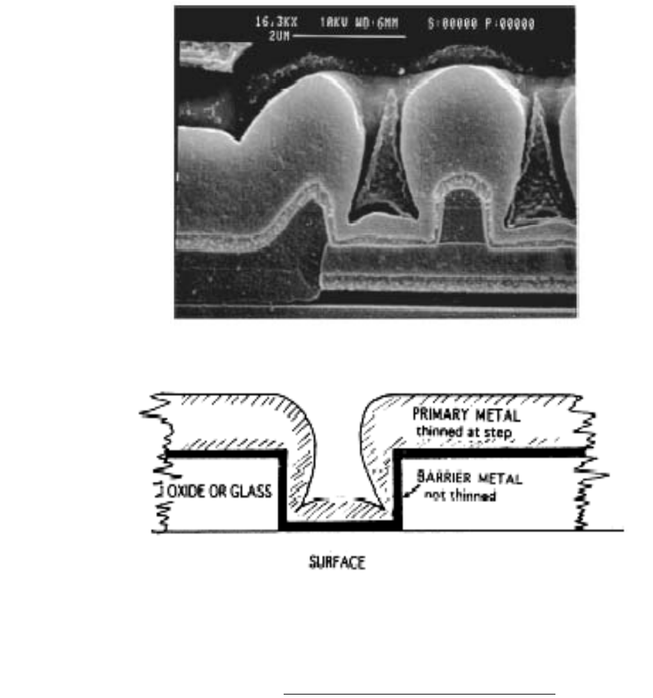
MIL-STD-883F METHOD 2018.4 18 June 2004 35 Figure 2018. 24 20% metalli zation c overage (bar rier metal inc lus ive) * * * *
MIL-STD-883F
METHOD 2018.4
18 June 2004
34
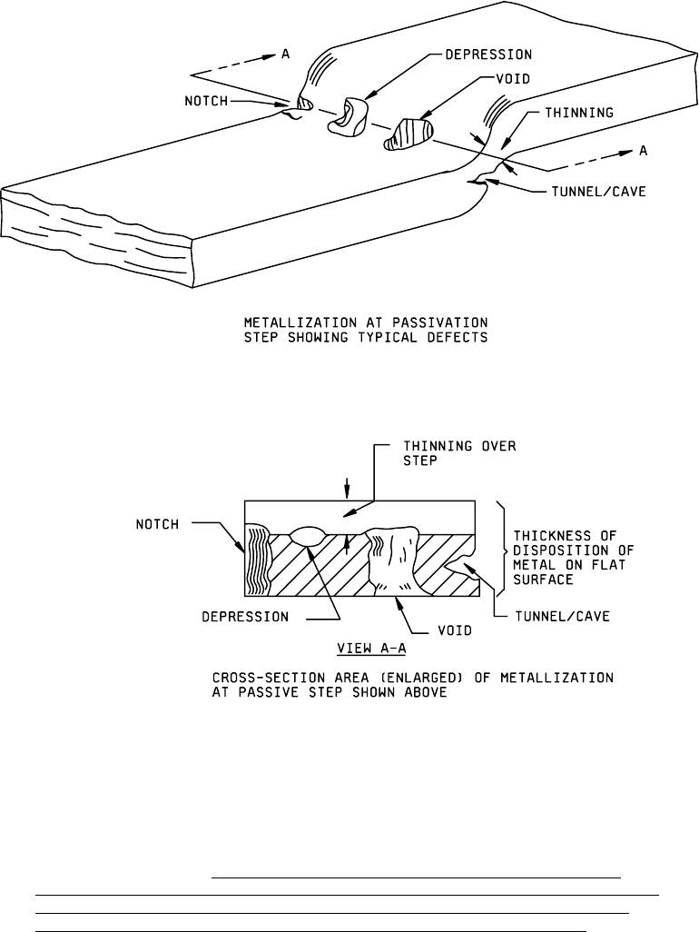
FIGURE 2018-23. Concept of reduction of cross-sectional area of metallization
as accept/reject criteria (any combination of defects and thinning over a step which reduces
the cross-sectional area of the metal to less than the percentage defined within 3.7.2 of
metal cross-sectional area as deposited on the flat surface) is cause for rejection
.
MIL-STD-883F
METHOD 2018.4
18 June 2004
35
Figure 2018.24 20% metallization coverage (barrier metal inclusive)
*
*
*
*

MIL-STD-883F
METHOD 2018.4
18 June 2004
36
APPENDIX A
Metal integrity alternate to SEM inspection
10. PURPOSE
. Metal integrity is achieved through a system of designing and building in quality and reliability. It is not
practical or cost effective to rely solely on end-of-line testing to ensure metal integrity. This procedure provides a system for
designing, building, and monitoring a metal system that withstands the operating conditions of the device for the specified
lifetime.
20. SCOPE
20.1 Utilization of this method provides an alternate to the requirements defined in TM2018. This procedure must be
used in conjunction with the requirements of alternate 2 of TM5004, paragraph 3.3.1 as it applies to metallization.
20.2 This procedure describes a method by which metal integrity is assured through a combination of design rules and
techniques, process development, manufacturing controls and end-of-line screening and reliability testing.
20.2.1 Design controls
.
a. Reliability rules.
b. Layout rules.
c. Rules checking.
d. Process development.
20.2.2 Manufacturing controls
. Statistical control of the manufacturing process and equipment defect and foreign
material control.
20.2.3 Reliability testing
. Accelerated tests.
30. DEFINITIONS
Lifetime
. The mean time to failure of a technology at operating conditions defined to be normal. The mean time to
failure is measured on a large sample of devices stressed at temperatures and current densities well above the normal
operating conditions and extrapolated to normal operating temperature and current density.
Current density
. The maximum allowable current density calculated as described in appendix A of MIL-PRF-38535.
Specification limits
. Minimum or maximum boundaries for the value of a measured parameter. Material whose
measured values are beyond these boundaries must be reviewed and dispositioned.
Worst case operating conditions
. Conditions of current and temperature at which a device would normally
operate, that would result in the greatest likelihood of failure.